Κατέβασμα παρουσίασης
Η παρουσίαση φορτώνεται. Παρακαλείστε να περιμένετε

1
Μέθοδοι και Εργαλεία για τη Διαχείριση Δικτύων IPv6

2
Τί ισχύει για τη διαχείριση στο IPv6 n Απαραίτητο στοιχείο για να επιτευχθεί η ομαλή μετάβαση στο νέο πρωτόκολλο –Απαιτούνται αντίστοιχα πρότυπα λειτουργικότητας και ποιότητας με το IPv4 n Ο σωστός σχεδιασμός του δικτύου αναδεικνύει τα κύρια τμήματα του και τους χρήστες (με τις ανάγκες τους) σε κάθε ένα από αυτά n Περιοχές διαχείρισης: –Παρακολούθηση της καθημερινής λειτουργίας του δικτύου –Εξέλιξη και βελτιστοποίηση του δικτύου n Η διαχείριση στο IPv6 δε διαθέτει οριστικές λύσεις σε όλους τους τομείς –Ορισμένα πρωτόκολλα είναι ακόμη σε εξέλιξη –Δεν υπάρχουν εργαλεία για όλες τις διαχειριστικές ανάγκες
 σε κάθε ένα από αυτά n Περιοχές διαχείρισης: –Παρακολούθηση της καθημερινής λειτουργίας του δικτύου –Εξέλιξη και βελτιστοποίηση του δικτύου n Η διαχείριση στο IPv6 δε διαθέτει οριστικές λύσεις σε όλους τους τομείς –Ορισμένα πρωτόκολλα είναι ακόμη σε εξέλιξη –Δεν υπάρχουν εργαλεία για όλες τις διαχειριστικές ανάγκες")
3
Διαδικασία Υλοποίησης IPv6 σε ένα Δίκτυο Φάση 1 n Σχεδιασμός της μορφής του δικτύου –Ευρύτερες και μικρότερες δικτυακές περιοχές –Περιοχές ειδικών αναγκών και ειδικών λειτουργιών (VLANs, κ.λπ.) –Ορισμός των διαχειριστικών οντοτήτων και των περιοχών ευθύνης στο δίκτυο –Προσδιορισμός των ροών πληροφορίας διαχείρισης –Καθορισμός των αναγκών στην ασφάλεια: »Για τους χρήστες και τις εφαρμογές »Για το ίδιο το δίκτυο (διαχειριστική πληροφορία, δικτυακές συσκευές, διαδικασίες διαχείρισης) –Σχεδιασμός της διαδικασίας μετάβασης στο νέο πρωτόκολλο και της χρήσης πιθανών μεταβατικών μηχανισμών (περιοχές IPv6 μέσα σε δίκτυο IPv4 και αντίστροφα)
 –Ορισμός των διαχειριστικών οντοτήτων και των περιοχών ευθύνης στο δίκτυο –Προσδιορισμός των ροών πληροφορίας διαχείρισης –Καθορισμός των αναγκών στην ασφάλεια: »Για τους χρήστες και τις εφαρμογές »Για το ίδιο το δίκτυο (διαχειριστική πληροφορία, δικτυακές συσκευές, διαδικασίες διαχείρισης) –Σχεδιασμός της διαδικασίας μετάβασης στο νέο πρωτόκολλο και της χρήσης πιθανών μεταβατικών μηχανισμών (περιοχές IPv6 μέσα σε δίκτυο IPv4 και αντίστροφα)")
4
Διαδικασία Υλοποίησης IPv6 σε ένα Δίκτυο (2) Φάση 2 n Υλοποίηση διπλού περιβάλλοντος IPv4/IPv6 n Σταδιακή μετάβαση στο IPv6 συστημάτων μη κρίσιμων λειτουργιών –Επιτρέπει την αξιολόγηση της σταθερότητας της λειτουργίας του IPv6 στο δικτυακό εξοπλισμό και σε μη κρίσιμα συστήματα –Αναπτύσσονται οι διαδικασίες διαχείρισης –Χρήση μηχανισμών μετάβασης: σήραγγες (tunnels), πύλες (gateways) κ.λπ. για την επικοινωνία περιοχών αποκλειστικά IPv6 Φάση 3 n Μετάβαση όλων των συστημάτων αποκλειστικά σε IPv6 n Χρήση αποκλειστικά IPv6 στο δίκτυο

5
Προτυποποίηση Πρωτοκόλλων Διαχείρισης n Οι κύριοι κατασκευαστές δικτυακού εξοπλισμού υποστηρίζουν τη χρήση SNMP πάνω από IPv6 και παρέχουν agents –Η διαχείριση συσκευών αποκλειστικά IPv4 είναι δυνατή επειδή στα περισσότερα δίκτυα υπάρχει υποστήριξη dual stack –Από πλευράς agents γενικής χρήσης υπάρχει πλήρης υποστήριξη του SNMP- IPv6 από το net-snmp που υλοποιεί τις νέες MIBs –Ο αριθμός των εφαρμογών που χρησιμοποιούν το SNMP-IPv6 παραμένει μικρός. Τα Openview και CiscoWorks προσφέρουν σταδιακά υποστήριξη IPv6 σε επίπεδο MIB αλλά στις περισσότερες περιπτώσεις η πρόσβαση γίνεται με IPv4 n Νέα textual conventions υποστηρίζουν IPv4 και IPv6 για την αναπαράσταση IPs στις MIBs –RFC 3291 –Eχει προωθηθεί η ενοποίηση πινάκων πληροφορίας για τα IP, TCP και UDP σε οποιοδήποτε από τα δύο περιβάλλοντα

6
Προτυποποίηση Πρωτοκόλλων Διαχείρισης (2) n Άλλα πρότυπα διαχείρισης έχουν επιτύχει διαφορετικούς βαθμούς μετάβασης στο IPv6: –Το RADIUS έχει προτυποποιηθεί στο IPv6 (RFC 3162) αλλά δε μπορεί να χρησιμοποιηθεί σε μεγάλα δίκτυα. Για το λόγο αυτό το IETF έχει ορίσει ένα πρωτόκολλο αντικατάστασης του, το DIAMETER. Έτσι δεν υπάρχουν υλοποιήσεις του RADIUS σε IPv6 –Το DIAMETER ορίζεται στο RFC 3588. Υπάρχει διαθέσιμη υλοποίηση του –Τα COPS και WBEM (Web-Based Enterprise Manager) έχουν προσαρμοστεί, όπως και τα μοντέλα πληροφορίας και οι πολιτικές που ορίζουν για τη διαχείριση δικτύων IPv6. Δεν υπάρχουν όμως διαθέσιμες υλοποιήσεις –Το Kerberos V έχει μερικώς μεταφερθεί στο IPv6
 έχουν προσαρμοστεί, όπως και τα μοντέλα πληροφορίας και οι πολιτικές που ορίζουν για τη διαχείριση δικτύων IPv6. Δεν υπάρχουν όμως διαθέσιμες υλοποιήσεις –Το Kerberos V έχει μερικώς μεταφερθεί στο IPv6.")
7
Προτυποποίηση Πρωτοκόλλων Διαχείρισης (3) n Το Netflow της Cisco υποστηρίζει την εξαγωγή στατιστικών για ροές IPv6 μόνον στην έκδοση 9 –Υποστηρίζεται από το IOS 12.3T –Συλλέκτες πληροφορίας Netflow που να υποστηρίζουν IPv6 υπάρχουν από τη Cisco και ακαδημαϊκές πηγές
 n Το Netflow της Cisco υποστηρίζει την εξαγωγή στατιστικών για ροές IPv6 μόνον στην έκδοση 9 –Υποστηρίζεται από το IOS 12.3T –Συλλέκτες πληροφορίας Netflow που να υποστηρίζουν IPv6 υπάρχουν από τη Cisco και ακαδημαϊκές πηγές")
8
Διαχείριση στο IPv68/15 Μηχανισμοί Μετάβασης n Πρόκειται για τους μηχανισμούς που επιτρέπουν την (προσωρινή...) συνύπαρξη περιοχών IPv4 και IPv6 –Μηχανισμοί εγκατάστασης σηράγγων (tunnels) μέσα από δικτυακές περιοχές που δεν υποστηρίζουν το επιθυμητό πρωτόκολλο και ενθυλάκωσης του περιεχομένου που πρέπει να περάσει διαμέσου αυτών. Επίσης, μηχανισμοί μετάφρασης ανάμεσα στα δύο πρωτόκολλα –6to4, Intra-Site Automatic Tunnel Addressing Protocol (ISATAP), Dual-stack Transition Mechanism (DSTM) n Αποτελούν ειδική διαχειριστική περίπτωση στο IPv6 n Απαιτούν προσεκτικό σχεδιασμό για: –Τα σημεία που θα εγκατασταθούν –Τον έλεγχο πρόσβασης σε αυτούς και τις πολιτικές χρήσης τους από τους χρήστες –Τις πολιτικές λειτουργίας, ειδικά στο θέμα της «αναμετάδοσης» εσωτερικής ή εξωτερικής κίνησης μέσω του 6to4 (6to4 relays)
, Dual-stack Transition Mechanism (DSTM) n Αποτελούν ειδική διαχειριστική περίπτωση στο IPv6 n Απαιτούν προσεκτικό σχεδιασμό για: –Τα σημεία που θα εγκατασταθούν –Τον έλεγχο πρόσβασης σε αυτούς και τις πολιτικές χρήσης τους από τους χρήστες –Τις πολιτικές λειτουργίας, ειδικά στο θέμα της «αναμετάδοσης» εσωτερικής ή εξωτερικής κίνησης μέσω του 6to4 (6to4 relays).")
9
Μηχανισμοί Μετάβασης (2) n Υπάρχουν σημαντικά κενά στη διαχείριση τους –Είναι δυνατόν να δημιουργήσουν προβλήματα διαχείρισης πόρων και ασφάλειας –Δεν ακόμα απόλυτα ξεκάθαρες οι διαχειριστικές ανάγκες και διαδικασίες που πρέπει να ακολουθηθούν –Αφορούν μηχανισμούς «ενθυλάκωσης» που είναι γνωστοί και κατανοητοί από το IPv4 –Εναλλακτικά μπορούν να τεθούν υπό βασικό έλεγχο (π.χ. αποδοχής ή όχι της κίνησης) με υπάρχοντες μηχανισμούς (π.χ. Firewalls)
 με υπάρχοντες μηχανισμούς (π.χ. Firewalls).")
10
Βασικά Εργαλεία Διαχείρισης n Διαχείριση Δικτύων Κορμού –ASPath Tree (http://carmen.ipv6.tilab.com/ipv6/tools/ASpath-tree/index.html) –Looking Glass (http://netmon.grnet.gr/lgv6.shtml) –IPFlow/Netflow (http://www.rrt.cr-picardie.fr/%7Efillot/nf6/http://www.cisco.com/warp/public/732/Tech/nmp/netflow/index.shtml) –Mping (http://mping.uninett.no/) –RIPE Test Traffic (TT) Server with IPv6 Support (http://www.ripe.net/ttm/ttm-ipv6.html) – NTUA: tt42 –Cricket (http://cricket.sourceforge.net/) –MRTG
 Server with IPv6 Support ( – NTUA: tt42 –Cricket ( –MRTG")
11
Βασικά Εργαλεία Διαχείρισης n Διαχείριση Δικτύων - Πελάτων –Argus (http://argus.tcp4me.com/) –Ethereal (http://www.ethereal.com/) –Multicast Beacon (http://dast.nlanr.net/Projects/Beacon/) –Iperf (http://dast.nlanr.net/Projects/Iperf/) –ntop (http://www.ntop.org/) n Γενική Διαχείριση –Nagios (http://www.nagios.org/) –RANCID (http://www.shrubbery.net/rancid/)

12
Προτάσεις για τη διαχείριση δικτύων IPv6 1. Αρχιτεκτονική –Ακολουθείται συγκεκριμένη διαδικασία σχεδιασμού και υλοποίησης του IPv6 σε ένα δίκτυο 2. Διαχειριστικές Εργασίες – Δίκτυα πελάτες –Χρησιμοποιείται ένα κοινό εργαλείο για τη διαπίστωση σωστής λειτουργίας υπηρεσιών και δικτυακών συνδέσεων (Argus, Nagios ή Ntop) –Εργαλεία παρακολούθησης της κίνησης (MRTG) –Χρησιμοποιούνται εργαλεία για την αξιολόγηση της απόδοσης των δικτυακών συνδέσεων «από άκρο σε άκρο» με τους παρόχους (ISPs) και το υπόλοιπο Διαδίκτυο (Iperf) –Χρειάζεται να υπάρχει δυνατότητα καταγραφής και ανάλυσης της κίνησης (Ethereal) –Προαιρετικά χρήση εργαλείων για τη διαχείριση των ρυθμίσεων των δικτυακών συσκευών (RANCID)
 –Εργαλεία παρακολούθησης της κίνησης (MRTG) –Χρησιμοποιούνται εργαλεία για την αξιολόγηση της απόδοσης των δικτυακών συνδέσεων «από άκρο σε άκρο» με τους παρόχους (ISPs) και το υπόλοιπο Διαδίκτυο (Iperf) –Χρειάζεται να υπάρχει δυνατότητα καταγραφής και ανάλυσης της κίνησης (Ethereal) –Προαιρετικά χρήση εργαλείων για τη διαχείριση των ρυθμίσεων των δικτυακών συσκευών (RANCID).")
13
Προτάσεις για τη διαχείριση δικτύων IPv6 (2) 3. Δίκτυα κορμού –Έλεγχος της κίνησης (MRTG, Cricket, Nagios) –Καταγραφή και ανάλυση της κίνησης (Netflow v9) –Παρακολούθησης της ομαλής λειτουργίας του δικτυακού εξοπλισμού (Nagios) –Έλεγχος της δρομολόγησης »Για παρακολούθηση των πολιτικών δρομολόγησης και τη γενική εικόνα της κατάστασης δρομολόγησης BGP(Border Gateway Protocol) (ASpath-tree) »Η παρακολούθηση παραμέτρων του BGP σε συγκεκριμένους δρομολογητές δε μπορεί να γίνει αυτόματα λόγω έλλειψης κατάλληλων εργαλείων SNMP και υλοποίησης των αντίστοιχων MIBs στο IPv6
 –Καταγραφή και ανάλυση της κίνησης (Netflow v9) –Παρακολούθησης της ομαλής λειτουργίας του δικτυακού εξοπλισμού (Nagios) –Έλεγχος της δρομολόγησης »Για παρακολούθηση των πολιτικών δρομολόγησης και τη γενική εικόνα της κατάστασης δρομολόγησης BGP(Border Gateway Protocol) (ASpath-tree) »Η παρακολούθηση παραμέτρων του BGP σε συγκεκριμένους δρομολογητές δε μπορεί να γίνει αυτόματα λόγω έλλειψης κατάλληλων εργαλείων SNMP και υλοποίησης των αντίστοιχων MIBs στο IPv6.")
14
14 Management Information Base ΙΙ, MIB-ΙΙ

15
15 Η δομή των πληροφοριών διαχείρισης n Ορισμός αντικειμένων διαχείρισης (RFC 1212) OBJECT-TYPE MACRO ::= OBJECT-TYPE MACRO ::= BEGIN BEGIN TYPE NOTATION ::="SYNTAX" type(ObjectSyntax) TYPE NOTATION ::="SYNTAX" type(ObjectSyntax) "ACCESS" Access "ACCESS" Access "STATUS" Status "STATUS" Status DescrPart DescrPart ReferPart ReferPart IndexPart IndexPart DefValPart DefValPart VALUE NOTATION ::= value (VALUE ObjectName) VALUE NOTATION ::= value (VALUE ObjectName) Access ::= "read-only"|"read-write"|"write-only"|"not-accessible" Access ::= "read-only"|"read-write"|"write-only"|"not-accessible" Status ::= "mandatory"|"optional"| "obsolete"| "deprecated" Status ::= "mandatory"|"optional"| "obsolete"| "deprecated" DescrPart::= DESCRIPTION" value (description DisplayString)| empty DescrPart::= DESCRIPTION" value (description DisplayString)| empty ReferPart::= "REFERENCE" value (reference DisplayString)| empty ReferPart::= "REFERENCE" value (reference DisplayString)| empty IndexPart ::= "INDEX" "{" IndexTypes "}” | empty IndexPart ::= "INDEX" "{" IndexTypes "}” | empty IndexTypes ::= IndexType | IndexTypes "," IndexType IndexTypes ::= IndexType | IndexTypes "," IndexType IndexType ::= value (indexobject ObjectName)| type (indextype) IndexType ::= value (indexobject ObjectName)| type (indextype) DefValPart ::= "DEFVAL" "{" value (defvalue ObjectSyntax) "}" DefValPart ::= "DEFVAL" "{" value (defvalue ObjectSyntax) "}" | empty | emptyEND IndexSyntax::=CHOICE{number INTEGER (0..MAX),string OCTET STRING, object OBJECT IDENTIFIER, object OBJECT IDENTIFIER, address NetworkAddress,ipAddress IpAddress }
 OBJECT-TYPE MACRO ::= OBJECT-TYPE MACRO ::= BEGIN BEGIN TYPE NOTATION ::= SYNTAX type(ObjectSyntax) TYPE NOTATION ::= SYNTAX type(ObjectSyntax) ACCESS Access ACCESS Access STATUS Status STATUS Status DescrPart DescrPart ReferPart ReferPart IndexPart IndexPart DefValPart DefValPart VALUE NOTATION ::= value (VALUE ObjectName) VALUE NOTATION ::= value (VALUE ObjectName) Access ::= read-only | read-write | write-only | not-accessible Access ::= read-only | read-write | write-only | not-accessible Status ::= mandatory | optional | obsolete | deprecated Status ::= mandatory | optional | obsolete | deprecated DescrPart::= DESCRIPTION value (description DisplayString)| empty DescrPart::= DESCRIPTION value (description DisplayString)| empty ReferPart::= REFERENCE value (reference DisplayString)| empty ReferPart::= REFERENCE value (reference DisplayString)| empty IndexPart ::= INDEX { IndexTypes } | empty IndexPart ::= INDEX { IndexTypes } | empty IndexTypes ::= IndexType | IndexTypes , IndexType IndexTypes ::= IndexType | IndexTypes , IndexType IndexType ::= value (indexobject ObjectName)| type (indextype) IndexType ::= value (indexobject ObjectName)| type (indextype) DefValPart ::= DEFVAL { value (defvalue ObjectSyntax) } DefValPart ::= DEFVAL { value (defvalue ObjectSyntax) } | empty | emptyEND IndexSyntax::=CHOICE{number INTEGER (0..MAX),string OCTET STRING, object OBJECT IDENTIFIER, object OBJECT IDENTIFIER, address NetworkAddress,ipAddress IpAddress }")
16
16 Management Information Base ΙΙ, MIB-ΙΙ Παράδειγμα ορισμού πίνακα (1/2) Παράδειγμα ορισμού πίνακα (1/2) tcpConnTable OBJECT-TYPE SYNTAX SEQUENCE OF TcpConnEntry SYNTAX SEQUENCE OF TcpConnEntry ACCESS not-accessible ACCESS not-accessible STATUS mandatory STATUS mandatory DESCRIPTION DESCRIPTION "A table containing TCP connection-specific information." "A table containing TCP connection-specific information." ::= { tcp 13 } tcpConnEntry OBJECT-TYPE SYNTAX TcpConnEntry SYNTAX TcpConnEntry ACCESS not-accessible ACCESS not-accessible STATUS mandatory STATUS mandatory DESCRIPTION DESCRIPTION "Information about a particular current TCP connection. "Information about a particular current TCP connection. An object of this type is transient, in that it ceases to An object of this type is transient, in that it ceases to exist when (or soon after)the connection makes the transition to the CLOSED state." INDEX { tcpConnLocalAddress, tcpConnLocalPort, tcpConnRemAddress, tcpConnRemPort } INDEX { tcpConnLocalAddress, tcpConnLocalPort, tcpConnRemAddress, tcpConnRemPort } ::= { tcpConnTable 1 } ::= { tcpConnTable 1 }
the connection makes the transition to the CLOSED state. INDEX { tcpConnLocalAddress, tcpConnLocalPort, tcpConnRemAddress, tcpConnRemPort } INDEX { tcpConnLocalAddress, tcpConnLocalPort, tcpConnRemAddress, tcpConnRemPort } ::= { tcpConnTable 1 } ::= { tcpConnTable 1 }.")
17
IPv4 Addressing Notation n An IPv4 address consists of four bytes (32 bits). These bytes are also known as octets. For readability purposes, humans typically work with IP addresses in a notation called dotted decimal. This notation places periods between each of the four numbers (octets) that comprise an IP address. For example, an IP address that computers see as bytesoctetsbytesoctets 00001010 00000000 00000000 00000001 is written in dotted decimal as 10.0.0.1
 that comprise an IP address. For example, an IP address that computers see as bytesoctetsbytesoctets is written in dotted decimal as")
18
IPv4 Addressing Notation n Because each byte contains 8 bits, each octet in an IP address ranges in value from a minimum of 0 to a maximum of 255. Therefore, the full range of IP addresses is from 0.0.0.0 through 255.255.255.255. This represents a total of 4,294,967,296 possible IP addresses.

19
IPv6 Addressing Notation n IP addresses change significantly with IPv6. IPv6 addresses are 16 bytes (128 bits) long rather than four bytes (32 bits). This larger size means that IPv6 supports more than 300,000,000,000,000,000,000,000,000,000, 000,000,000 possible addresses! As an increasing number of cell phones and other consumer electronics expand their networking capability and require their own addresses, the smaller IPv4 address space will eventually run out and IPv6 become mandatory. IPv6 addresses are generally written in the following form: n hhhh:hhhh:hhhh:hhhh:hhhh:hhhh:hhhh:hhh h n In this full notation, pairs of IPv6 bytes are separated by a colon and each byte in turns is represented as a pair of hexadecimal numbers, like in the following example: E3D7:0000:0000:0000:51F4:9BC8:C0A8:6 420 n As shown above, IPv6 addresses commonly contain many bytes with a zero value. Shorthand notation in IPv6 removes these values from the text representation (though the bytes are still present in the actual network address) as follows: E3D7::51F4:9BC8:C0A8:6420
 long rather than four bytes (32 bits). This larger size means that IPv6 supports more than 300,000,000,000,000,000,000,000,000,000, 000,000,000 possible addresses. As an increasing number of cell phones and other consumer electronics expand their networking capability and require their own addresses, the smaller IPv4 address space will eventually run out and IPv6 become mandatory. IPv6 addresses are generally written in the following form: n hhhh:hhhh:hhhh:hhhh:hhhh:hhhh:hhhh:hhh h n In this full notation, pairs of IPv6 bytes are separated by a colon and each byte in turns is represented as a pair of hexadecimal numbers, like in the following example: E3D7:0000:0000:0000:51F4:9BC8:C0A8:6 420 n As shown above, IPv6 addresses commonly contain many bytes with a zero value. Shorthand notation in IPv6 removes these values from the text representation (though the bytes are still present in the actual network address) as follows: E3D7::51F4:9BC8:C0A8:6420.")
20
IPv6 Addressing Notation n IP addresses change significantly with IPv6. IPv6 addresses are 16 bytes (128 bits) long rather than four bytes (32 bits). This larger size means that IPv6 supports more than 300,000,000,000,000,000,000,000,000,000, 000,000,000 possible addresses!
 long rather than four bytes (32 bits). This larger size means that IPv6 supports more than 300,000,000,000,000,000,000,000,000,000, 000,000,000 possible addresses!.")
21
IPv6 Addressing Notation n As an increasing number of cell phones and other consumer electronics expand their networking capability and require their own addresses, the smaller IPv4 address space will eventually run out and IPv6 become mandatory. IPv6 addresses are generally written in the following form: hhhh:hhhh:hhhh:hhhh:hhhh:hhhh:hhhh:hhhh

22
IPv6 Addressing Notation n In this full notation, pairs of IPv6 bytes are separated by a colon and each byte in turn is represented as a pair of hexadecimal numbers, like in the following example: E3D7:0000:0000:0000:51F4:9BC8:C0A8:6420 n In this full notation, pairs of IPv6 bytes are separated by a colon and each byte in turns is represented as a pair of hexadecimal numbers, like in the following example: E3D7:0000:0000:0000:51F4:9BC8:C0A8:6420

23
IPv6 Addressing Notation n IPv6 addresses commonly contain many bytes with a zero value. Shorthand notation in IPv6 removes these values from the text representation (though the bytes are still present in the actual network address) as follows: E3D7::51F4:9BC8:C0A8:6420 n Finally, many IPv6 addresses are extensions of IPv4 addresses. In these cases, the rightmost four bytes of an IPv6 address (the rightmost two byte pairs) may be rewritten in the IPv4 notation.
 as follows: E3D7::51F4:9BC8:C0A8:6420 n Finally, many IPv6 addresses are extensions of IPv4 addresses. In these cases, the rightmost four bytes of an IPv6 address (the rightmost two byte pairs) may be rewritten in the IPv4 notation..")
24
IPv6/IPv4 Address Embedding n A transition from IPv4 to IPv6 will be required, which requires careful planning. It is anticipated that the migration from IPv4 to IPv6 will take several years. n IPv6 is backward compatible with IPv4, provided that special techniques are used. For example, to enable communication between "islands" of IPv6 devices connected by IPv4 networks, tunneling may be employed.

25
IPv6/IPv4 Address Embedding n To support IPv4/IPv6 compatibility, a scheme was developed to allow IPv4 addresses to be embedded within the IPv6 address structure. This method takes regular IPv4 addresses and puts them in a special IPv6 format so they are recognized as being IPv4 addresses by certain IPv6 devices.

26
IPv6/IPv4 Address Embedding n Since the IPv6 address space is so much bigger than that of IPv4, embedding the latter within the former is easy. The embedding address space is part of the reserved address block whose addresses begin with eight zero bits, but only a relatively small part of it. reserved address block reserved address block

27
IPv6/IPv4 Address Embedding n Two different embedding formats are used. Both have zeroes for the first 80 bits of the address, and put the embedded IPv4 address into the last 32 bits of the IPv6 address format. They differ on the value of the 16 remaining bits in between (bits 81 to 96, counting from the left): n The two embedding formats are used in order to indicate the capabilities of the device using the embedded address.
: n The two embedding formats are used in order to indicate the capabilities of the device using the embedded address..")
28
IPv4-Compatible IPv6 Addresses n These are special addresses assigned to IPv6-capable devices, such as so-called “dual stack” devices that speak both IPv4 and IPv6. They have all zeroes for the middle 16 bits; thus, they start off with a string of 96 zeroes, followed by the IPv4 address. An example of such an address, would be 0:0:0:0:0:0:101.45.75.219 in mixed notation, or more succinctly, ::101.45.75.219.

29
IPv6/IPv4 Address Embedding

30
30 Management Information Base ΙΙ, MIB-ΙΙ n Τύποι αντικειμένων διαχείρισης –βαθμωτά αντικείμενα (scalar objects): σε κάθε χρονική στιγμή έχουν μία μόνο τιμή (π.χ. το όνομα, ο αριθμός των διεπαφών ενός κόμβου) –πίνακες αντικειμένων (table objects): δισδιάστατοι πίνακες αντικειμένων (π.χ. ο πίνακας δρομολόγησης, ο πίνακας των συνδέσεων του πρωτοκόλλου TCP) n Τα group αντικειμένων
 –πίνακες αντικειμένων (table objects): δισδιάστατοι πίνακες αντικειμένων (π.χ. ο πίνακας δρομολόγησης, ο πίνακας των συνδέσεων του πρωτοκόλλου TCP) n Τα group αντικειμένων.")
31
Τα group αντικειμένων της ΜΙΒ- ΙΙ n system: γενικές πληροφορίες για το σύστημα n interfaces: πληροφορίες σε σχέση με τα χαρακτηριστικά και την κίνηση κάθε δικτυακής διεπαφής n at: πίνακας αντιστοίχησης διευθύνσεων IP με φυσικές διευθύνσεις n ip: πληροφορίες για την υλοποίηση και τη λειτουργία του πρωτοκόλλου IP n tcp: πληροφορίες για την υλοποίηση και τη λειτουργία του πρωτοκόλλου TCP n udp: πληροφορίες για την υλοποίηση και τη λειτουργία του πρωτοκόλλου UDP n egp: πληροφορίες για την υλοποίηση και τη λειτουργία του πρωτοκόλλου EGP (external gateway protocol) n transmission: ειδικές λεπτομέρειες για το μέσο μετάδοσης κάθε μίας διεπαφής αναλόγως το πρωτόκολλο όπως token ring, FDDI, κλπ. n snmp: πληροφορίες για την υλοποίηση και τη λειτουργία του πρωτοκόλλου SNMP

32
32 Management Information Base ΙΙ, MIB-ΙΙ Παράδειγμα ορισμού πίνακα Παράδειγμα ορισμού πίνακα TcpConnEntry ::= SEQUENCE { tcpConnStateΙNTEGER, tcpConnLocalAddressΙpAddress, tcpConnLocalPortINTEGER (0..65535), tcpConnRemAddressIpAddress, tcpConnRemPortINTEGER (0..65535) }
, tcpConnRemAddressIpAddress, tcpConnRemPortINTEGER ( ) }")
33
33 MIB-ΙΙ - system group sysDescr : περιγραφή συστήματος sysObjectID : αναγνωριστικό του κατασκευαστή sysUpTime : ο χρόνος από την τελευταία επανεκκίνηση sysContact : πληροφορίες υπευθύνου διαχείρισης sysName : όνομα κόμβου sysLocation : φυσική τοποθεσία κόμβου sysServices : μία τιμή που υποδηλώνει τις προσφερόμενες δικτυακές υπηρεσίες

34
34 MIB-ΙΙ - interface group n Σχόλια –Ο πίνακας ifTable είναι δισδιάστατος με 22 στήλες και γραμμές όσες οι δικτυακές διεπαφές –Το πρωτεύον κλειδί είναι το αντικείμενο ifIndex –Το αντικείμενο ifIndex είναι τύπου INTEGER με τιμές στο διάστημα 1..ifNumber

35
35 MIB-ΙΙ - ip group n Σχόλια –ipAddrTable : πληροφορίες για τις διευθύνσεις IP, μια γραμμή για κάθε διεύθυνση –ipRouteTable : πληροφορίες δρομολόγησης, μία γραμμή ανά προορισμό –ipNetToMediaTable : αντιστοίχιση μεταξύ διευθύνσεων IP και φυσικών διευθύνσεων

36
36 Το πρωτόκολλο διαχείρισης SNMPv1 n Λειτουργίες διαχείρισης –get:ανάκτηση συγκεκριμένης διαχειρίσιμης πληροφορίας –set: ενημέρωση της τιμής ενός διαχειρίσιμου αντικειμένου –trap:αναφορά απρόσμενων γεγονότων προς το σύστημα διαχείρισης n Θέματα ασφάλειας –Η σχέση ενός αντιπροσώπου με πολλούς σταθμούς διαχείρισης επιβάλλει έλεγχο ασφάλειας στα εξής: »Αυθεντικοποίηση: ο αντιπρόσωπος επιβάλλει περιορισμούς στην πρόσβαση της ΜΙΒ σε σταθμούς διαχείρισης με συγκεκριμένες αρμοδιότητες »Πολιτική πρόσβασης: ο αντιπρόσωπος επιβάλλει διαφορετικά δικαιώματα πρόσβασης σε διαφορετικούς σταθμούς διαχείρισης n Λύση: Η έννοια της κοινότητας (community)
")
37
Η έννοια της κοινότητας (community) στο SNMPv1 n SNMP community: n SNMP community: μία σχέση μεταξύ ενός αντιπροσώπου και ενός αριθμού σταθμών διαχείρισης σε θέματα αυθεντικοποίησης και ελέγχου πρόσβασης –Κάθε κοινότητα έχει ένα μοναδικό όνομα (community name) που ορίζεται τοπικά στον αντιπρόσωπο –Κάθε σταθμός διαχείρισης πρέπει να χρησιμοποιεί το κατάλληλο όνομα της κοινότητας για την επικοινωνία με τον αντιπρόσωπο n Αυθεντικοποίηση –Χρήση ονόματος κοινότητας σε κάθε μήνυμα SNMP χωρίς κρυπτογράφηση –Χρήση του ονόματος κοινότητας ως password: το μήνυμα θεωρείται αυθεντικό αν ο σταθμός διαχείρισης γνωρίζει το όνομα κοινότητας n Περιορισμένη μορφή ασφάλειας –Χρήση λειτουργίας set για παραβίαση συστημάτων
 στο SNMPv1 n SNMP community: n SNMP community: μία σχέση μεταξύ ενός αντιπροσώπου και ενός αριθμού σταθμών διαχείρισης σε θέματα αυθεντικοποίησης και ελέγχου πρόσβασης –Κάθε κοινότητα έχει ένα μοναδικό όνομα (community name) που ορίζεται τοπικά στον αντιπρόσωπο –Κάθε σταθμός διαχείρισης πρέπει να χρησιμοποιεί το κατάλληλο όνομα της κοινότητας για την επικοινωνία με τον αντιπρόσωπο n Αυθεντικοποίηση –Χρήση ονόματος κοινότητας σε κάθε μήνυμα SNMP χωρίς κρυπτογράφηση –Χρήση του ονόματος κοινότητας ως password: το μήνυμα θεωρείται αυθεντικό αν ο σταθμός διαχείρισης γνωρίζει το όνομα κοινότητας n Περιορισμένη μορφή ασφάλειας –Χρήση λειτουργίας set για παραβίαση συστημάτων")
38
Πολιτική πρόσβασης στο SNMPv1 (1) n Για κάθε κοινότητα ορίζεται ένα προφίλ (community profile) που αποτελείται από: »μία ΜΙΒ όψη (MIB view): ένα σύνολο αντικειμένων της ΜΙΒ που μπορεί και να μην ανήκουν στο ίδιο υπόδεντρο »ένα τρόπο πρόσβασης (access mode): READ-ONLY ή READ- WRITE αντιπρόσωπος SNMPσύνολο από SNMP σταθμούς διαχείρισης SNMP ΜΙΒ όψη SNMP τρόπος πρόσβασης SNMP κοινότητα SNMP προφίλ κοινότητας SNMP πολιτική πρόσβασης
 n Για κάθε κοινότητα ορίζεται ένα προφίλ (community profile) που αποτελείται από: »μία ΜΙΒ όψη (MIB view): ένα σύνολο αντικειμένων της ΜΙΒ που μπορεί και να μην ανήκουν στο ίδιο υπόδεντρο »ένα τρόπο πρόσβασης (access mode): READ-ONLY ή READ- WRITE αντιπρόσωπος SNMPσύνολο από SNMP σταθμούς διαχείρισης SNMP ΜΙΒ όψη SNMP τρόπος πρόσβασης SNMP κοινότητα SNMP προφίλ κοινότητας SNMP πολιτική πρόσβασης")
39
39 Πολιτική πρόσβασης στο SNMPv1 (2) n Πολιτική πρόσβασης (access policy) –Κανόνες συσχετισμού μεταξύ της κατηγορίας πρόσβασης ενός ΜΙΒ αντικειμένου και του τρόπου πρόσβασης μιας πολιτικής καθορίζουν ποιες λειτουργίες μπορούν να προσπελάσουν το αντικείμενο Παράδειγμα Η κατηγορία πρόσβασης του ΜΙ-ΙΙ αντικειμένου sysContact είναι RW. Για την κοινότητα public ο τρόπος πρόσβασης για το αντικείμενο αυτό έχει οριστεί ως RO. Κατά συνέπεια, μπορεί να είναι παράμετρος μόνο σε λειτουργίες get και trap

40
Η αναγνώριση στιγμιότυπων αντικειμένων διαχείρισης (1) n Αναγνώριση αντικειμένων με τυχαία πρόσβαση –Αντικείμενα πινάκων »Χρήση της τιμής του INDEX σε συνδυασμό με το OBJECT IDENTIFIER του αντικείμενου στήλης. Αν το αναγνωριστικό του αντικειμένου στήλης είναι y σε ένα πίνακα με αντικείμενα INDEX i1, i2, …, iN τότε το αναγνωριστικό του στιγμιότυπου ενός αντικειμένου είναι: y.(i1). (i2)…(iN) »Παράδειγμα: Το αναγνωριστικό της περιγραφής ifType της διεπαφής με ifIndex το 2 Το OBJECT IDENTIFIER του ifType είναι 1.3.6.1.2.1.2.2.1.3 Άρα για το ifType.2 είναι 1.3.6.1.2.1.2.2.1.3.2 –Βαθμωτά αντικείμενα »Χρήση του OBJECT IDENTIFIER του αντικείμενου σε συνδυασμό με το.0 Το αναγνωριστικό στιγμιότυπου του ifNumber είναι ifNumber.0 δηλαδή 1.3.6.1.2.1.2.1.0
. (i2)…(iN) »Παράδειγμα: Το αναγνωριστικό της περιγραφής ifType της διεπαφής με ifIndex το 2 Το OBJECT IDENTIFIER του ifType είναι Άρα για το ifType.2 είναι –Βαθμωτά αντικείμενα »Χρήση του OBJECT IDENTIFIER του αντικείμενου σε συνδυασμό με το.0 Το αναγνωριστικό στιγμιότυπου του ifNumber είναι ifNumber.0 δηλαδή")
41
Η αναγνώριση στιγμιότυπων αντικειμένων διαχείρισης (2) n Αναγνώριση αντικειμένων με λεξικογραφική σειρά –Χρήση της λεξικογραφικής σειράς των OBJECT IDENTIFIERS που είναι σειρά ακεραίων –Preorder traversal root 1 1.2 1.1 1.2.1 2 2.1 2.1.1 2.1.1.12.1.1.22.1.1.3 1 1 1 1 1 1 2 2 2 3 Αρχή Τέλος
 n Αναγνώριση αντικειμένων με λεξικογραφική σειρά –Χρήση της λεξικογραφικής σειράς των OBJECT IDENTIFIERS που είναι σειρά ακεραίων –Preorder traversal root Αρχή Τέλος")
42
SNMPv1 PDUs ΔιαχειριστήςΑντιπρόσωπος GetRequest PDU GetResponse PDU Αντιπρόσωπος GetNextRequest PDU GetResponse PDU Διαχειριστής Αντιπρόσωπος SetRequest PDU GetResponse PDU ΔιαχειριστήςΑντιπρόσωπος Trap PDU

43
SNMPv1 GetRequest PDU n Απαιτεί τη χρήση αναγνωριστικών στιγμιότυπων αντικειμένων (ανάκτηση φύλων του ΜΙΒ δέντρου) n Παραδείγματα: –Ανάκτηση των τιμών των βαθμωτών αντικειμένων sysDescr, sysName και ifNumber GetRequest(sysDescr.0, sysName.0, ifNumber.0) GetResponse((sysDescr.0 = “…”), (sysName.0 = “…”), (ifNumber.0 = 3)) –Ανάκτηση των τιμών των αντικειμένων στήλης του πίνακα ifTable ifIndex, ifType και ifSpeed για τη διεπαφή 2 GetRequest(ifIndex.2, ifType.2, ifSpeed.2) GetResponse((ifIndex.2 = 2), (ifType.2 = ethernetCsmacd(6)), (ifSpeed.2 = 10000000))
 n Παραδείγματα: –Ανάκτηση των τιμών των βαθμωτών αντικειμένων sysDescr, sysName και ifNumber GetRequest(sysDescr.0, sysName.0, ifNumber.0) GetResponse((sysDescr.0 = … ), (sysName.0 = … ), (ifNumber.0 = 3)) –Ανάκτηση των τιμών των αντικειμένων στήλης του πίνακα ifTable ifIndex, ifType και ifSpeed για τη διεπαφή 2 GetRequest(ifIndex.2, ifType.2, ifSpeed.2) GetResponse((ifIndex.2 = 2), (ifType.2 = ethernetCsmacd(6)), (ifSpeed.2 = ))")
44
SNMPv1 GetNextRequest PDU n Επιστρέφει την τιμή του στιγμιότυπου του αντικειμένου που είναι το επόμενο λεξικογραφικά από το όρισμα n Παραδείγματα: »Ανάκτηση των τιμών των βαθμωτών αντικειμένων sysDescr, sysName και ifNumber GetNextRequest(sysDescr, sysName, ifNumber) GetResponse((sysDescr.0 = “…”), (sysName.0 = “…”), (ifNumber.0 = 3)) »Ανάκτηση των τιμών των αντικειμένων στήλης του πίνακα ifTable ifIndex, ifType και ifSpeed για τη διεπαφή 2 GetNextRequest(ifIndex, ifType, ifSpeed) GetResponse((ifIndex.1 = 1), (ifType.1 = atm(37)), (ifSpeed.1 = 155000000)) GetNextRequest(ifIndex.1, ifType.1, ifSpeed.1) GetResponse((ifIndex.2 = 2), (ifType.2 = ethernetCsmacd(6)), (ifSpeed.2 = 10000000)) GetNextRequest(ifIndex.2, ifType.2, ifSpeed.2) GetResponse((ifDescr.1 = “…”), (ifMtu.1 =... ), (ifPhysAddress.1 =... ))
, (ifPhysAddress.1 =... )).")
45
SNMPv1 SetRequest και Trap PDUs n SetRequest –Αλλαγή της τιμής αντικειμένων που έχουν κατηγορία πρόσβασης RW –Παράδειγμα »Αλλαγή της κατάστασης της διεπαφής 2 σε testing SetRequest(ifStatus.2 = 3) GetResponse(ifStatus.2 = 3) n Trap –Γενικά είδη traps »coldStart(0) : αναπάντεχη επανεκκίνηση λόγω σημαντικής ζημιάς »warmStart(1): επανεκκίνηση ρουτίνας του δαίμονα SNMP »linkDown(2): πτώση επικοινωνιακής γραμμής »linkUp(3): επανεκκίνηση επικοινωνιακής γραμμής »authenticationFailure (4): λήψη μη αυθεντικού μηνύματος »egpNeighborLoss(5): πτώση EGP γειτονικού κόμβου »enterpriseSpecific(6): συγκεκριμένο γεγονός που αναγνωρίζει ο κατασκευαστής
 GetResponse(ifStatus.2 = 3) n Trap –Γενικά είδη traps »coldStart(0) : αναπάντεχη επανεκκίνηση λόγω σημαντικής ζημιάς »warmStart(1): επανεκκίνηση ρουτίνας του δαίμονα SNMP »linkDown(2): πτώση επικοινωνιακής γραμμής »linkUp(3): επανεκκίνηση επικοινωνιακής γραμμής »authenticationFailure (4): λήψη μη αυθεντικού μηνύματος »egpNeighborLoss(5): πτώση EGP γειτονικού κόμβου »enterpriseSpecific(6): συγκεκριμένο γεγονός που αναγνωρίζει ο κατασκευαστής")
46
Policy based management

47
Policy n Rule governing choices in behavior of the system n Derived from enterprise goals and service level agreement (SLA) n Need to specify and modify policies without coding into automated agents n Policies are persistent, but can be dynamically modified Change system behavior without modifying implementation
 n Need to specify and modify policies without coding into automated agents n Policies are persistent, but can be dynamically modified Change system behavior without modifying implementation")
48
Policy-based Network Management (PBNM) n Performs network management based on policies n Enables a manager to specify what he wants to do, the end result, without having to know how to accomplish it for the specific devices n Policies typically relate to QoS or Security –Quality of Service : bandwidth, latency, priority, DiffServ –Security : authentication, authorization, access control, audit
 n Performs network management based on policies n Enables a manager to specify what he wants to do, the end result, without having to know how to accomplish it for the specific devices n Policies typically relate to QoS or Security –Quality of Service : bandwidth, latency, priority, DiffServ –Security : authentication, authorization, access control, audit")
49
Why policy? n facilitates the dynamic change of behavior of a distributed management system n permits the reuse of the managers in different environments Monitor Control actions Control actions Decisions Events Manager Policies Managed Objects

50
IETF/DMTF Approach ( Distributed Management task Force ) n Directory Enabled Networks (DEN) n Policy Framework n Policy Architecture n Possible Implementation Protocols –Common Open Policy Service (COPS) –Lightweight Directory Access Protocol (LDAP) n Policy Standards
 n Directory Enabled Networks (DEN) n Policy Framework n Policy Architecture n Possible Implementation Protocols –Common Open Policy Service (COPS) –Lightweight Directory Access Protocol (LDAP) n Policy Standards")
51
Directory Enabled Networks (DEN) n Refers to the industry initiative, sponsored by DMTF n Acts as a repository for information about users and computing resources, network devices, services and applications n Developed as an extension to Common Information Model (CIM) –DEN information model adds network devices & services to the CIM information model An information model that defines management abstraction of –profiles and policies –devices, protocols, and services
 n Refers to the industry initiative, sponsored by DMTF n Acts as a repository for information about users and computing resources, network devices, services and applications n Developed as an extension to Common Information Model (CIM) –DEN information model adds network devices & services to the CIM information model An information model that defines management abstraction of –profiles and policies –devices, protocols, and services")
52
DEN (2) n Implementation in directory services that support LDAP as the access control n Helps to deploy QoS –Can be deployed from central console that creates policies in a directory –Automatically distributes configurations to network devices, operation systems, and applications Allows for PBNM using directories as the underlying repository of policy information
 n Implementation in directory services that support LDAP as the access control n Helps to deploy QoS –Can be deployed from central console that creates policies in a directory –Automatically distributes configurations to network devices, operation systems, and applications Allows for PBNM using directories as the underlying repository of policy information")
53
LDAP Lightweight Directory Access Protocol (LDAP) Lightweight Directory Access Protocol (LDAP) A client-server protocol specifically designed for accessing directories over a network. A client-server protocol specifically designed for accessing directories over a network. Defines standard communications methods for storing and accessing information in directories Defines standard communications methods for storing and accessing information in directories A “light” version of X.500 A “light” version of X.500

54
Policy Framework n Based on object oriented Common Information Model (CIM) with mapping onto LDAP schema n Policy of the form: –If a set of conditions is satisfied, then perform a set of actions n Specifies components of policy as objects n Uses directory for storing policies but not for grouping
 with mapping onto LDAP schema n Policy of the form: –If a set of conditions is satisfied, then perform a set of actions n Specifies components of policy as objects n Uses directory for storing policies but not for grouping")
58
Example Policies n Provide high QoS to nightly backup on server at IP address 141.223.2.15 from 2-4 a.m. on weeknights and Saturdays If ( ((srcIPaddress == 141.223.2.15) || (destIPaddress == 141.223.2.15)) && (timeOfDay = 0200-0400) && (dayOfWeek = _MTWRFS) ) then priority == 6 endif
 || (destIPaddress == )) && (timeOfDay = ) && (dayOfWeek = _MTWRFS) ) then priority == 6 endif.")
59
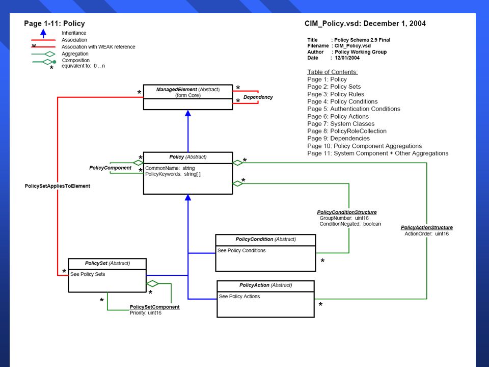
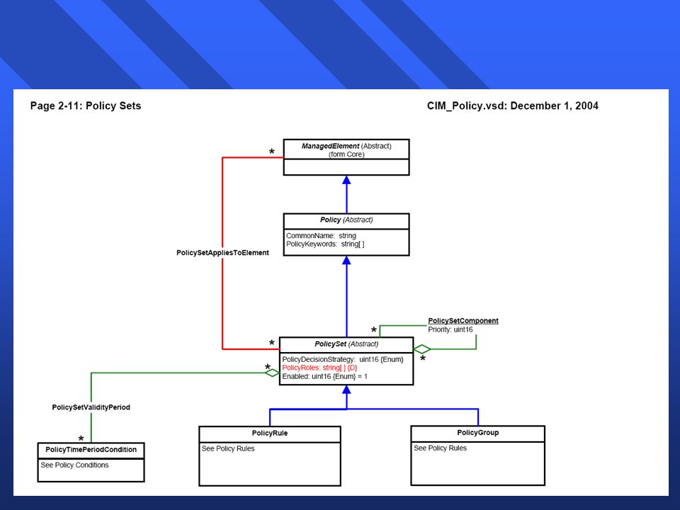
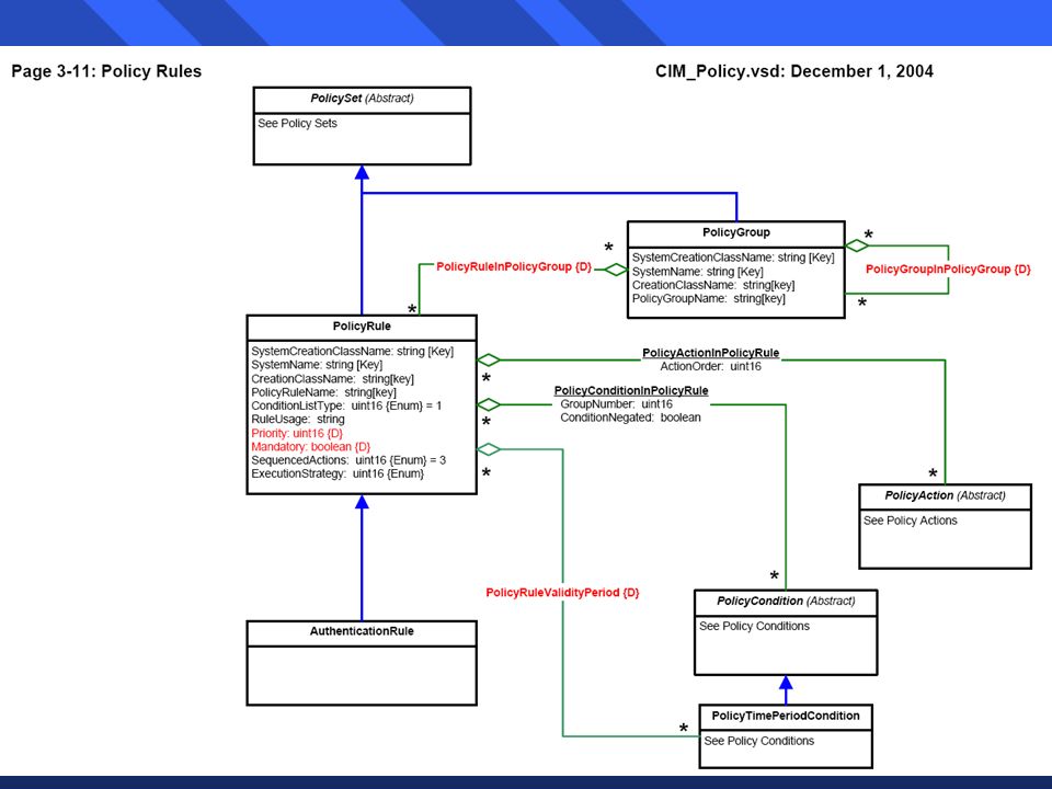
Policy Schema Policy Group Policy Condition Policy validity Period condition Policy Action Range of Time Time Masks Month of year Day of Month Day of Week Time of day Policy Rule 0..n Contained policy groups Contained policy rules Contained policy conditions Contained policy actions

60
Schema Concepts n Policy group is a set of related policy rules n Each policy rule component (condition, action) is stored as an LDAP object n Can reuse (share) policy component objects between multiple rules to avoid re-specifying multiple rules - can use the same period condition object
 is stored as an LDAP object n Can reuse (share) policy component objects between multiple rules to avoid re-specifying multiple rules - can use the same period condition object")
61
IETF Policy Architecture Policy Management Application Policy Consumer (PDP) Policy Target (PEP) Policy Repository (e.g. Directory, DB) User interface Conflict detection Notification generation Management information repository Policy Decision Point Policy translation Policy Enforcement Point Network element interface Policy rules Notification Status & Config. Info. Repository Access Protocol (e.g. LDAP) Policy Protocol (e.g.COPS …) Policy Server
 User interface Conflict detection Notification generation Management information repository Policy Decision Point Policy translation Policy Enforcement Point Network element interface Policy rules Notification Status & Config. Info. Repository Access Protocol (e.g. LDAP) Policy Protocol (e.g.COPS …) Policy Server.")
62
Policy Management Application n Policy Editing n Policy Presentation n Rule Translation n Rule Validation n Global Conflict Resolution

63
Policy Repository n Storage n Search n Retrieval

64
Policy Consumer n Receives policy and translates it into format applicable to target n Knows about target capabilities n Policy Decision Point (PDP) –makes policy decisions based on policy conditions –configures target to enforce policy such as access list, priority Q relating to packet address n Executes policy rule translation & policy transformation n Each target is controlled by one consumer n Consumer may control multiple targets
 –makes policy decisions based on policy conditions –configures target to enforce policy such as access list, priority Q relating to packet address n Executes policy rule translation & policy transformation n Each target is controlled by one consumer n Consumer may control multiple targets")
65
Policy Target n Policy Enforcement Point (PEP) n A specific functional feature (interface) of a device such as priority queuing, committed access rate for a router –e.g., a router with 2 interfaces and 4 manageable features for each interface will have 8 targets n A sophisticated device may include both PDP and PEPs Optionally, executes policy rule validation
 n A specific functional feature (interface) of a device such as priority queuing, committed access rate for a router –e.g., a router with 2 interfaces and 4 manageable features for each interface will have 8 targets n A sophisticated device may include both PDP and PEPs Optionally, executes policy rule validation")
66
Policy-based Management Scenario n Administrator makes a new policy or retrieves existing policy from directory service using LDAP and views or edits policy n Administrator associates the policy with policy targets n Policy and association with targets is stored in the repository via LDAP n The associated consumer for each target is notified that a new policy is available n The consumer obtains the policy from the repository via LDAP e.g., using query to find the policy n The consumer processes the policy and configures the targets using target-specific mechanism n For each target which received policy data, the consumer provides status information back to the policy management application

67
PEP – PDP Interaction Example PEP RSVP Router PDP Policy Server (1) Event e.g. RSVP Request (5) RSVP Request (2) REQ: Request(Source addr, etc) (3) DEC: Decision(resources) (4) Reserve resources Can also pre-configure devices with policy data, so they do not have to query PDP on every event-provisioning
 RSVP Request (2) REQ: Request(Source addr, etc) (3) DEC: Decision(resources) (4) Reserve resources Can also pre-configure devices with policy data, so they do not have to query PDP on every event-provisioning.")
68
Possible Implementation Protocols Policy Management Application Policy Consumer (PDP) Policy Target (PEP) Policy Repository (e.g. Directory, DB) Notification HTTP, COPS, SNMP Status & Config. Info. HTTP, COPS, SNMP LDAP, HTTP, COPS, SNMP HTTP, COPS, SNMP Policy Server LDAP, HTTP, COPS, SNMP
 Notification HTTP, COPS, SNMP Status & Config. Info. HTTP, COPS, SNMP LDAP, HTTP, COPS, SNMP HTTP, COPS, SNMP Policy Server LDAP, HTTP, COPS, SNMP.")
69
COPS n Common Open Policy Service (COPS) n Defined by IETF n Common protocol between elements and policy server n Client-server protocol for PEP to send status updates, requests to remote PDP to get back policy decisions n Provide mechanisms to push/pull policies
 n Defined by IETF n Common protocol between elements and policy server n Client-server protocol for PEP to send status updates, requests to remote PDP to get back policy decisions n Provide mechanisms to push/pull policies")
70
Policy Provisioning QoS Provisioning RSVP (Resource Reservation Protocol) admission control VPN connectivity Policy-based Routing etc. COPS Usage

71
n Operations –Request(REQ):PEP PDP –Decision(DEC):PDP PEP –Report State(RPT):PEP PDP –Delete Request State(DRS): PEP PDP –Synchronize State Req(SSQ): PDP PEP –Client-Open(OPN): PEP PDP –Client-Accept(CAT):PDP PEP –Client-Close(CC):PEP PDP –Keep-Alive(KA):PEP PDP –Synchronize Complete(SSC): PEP PDP COPS Messages
:PEP PDP –Decision(DEC):PDP PEP –Report State(RPT):PEP PDP –Delete Request State(DRS): PEP PDP –Synchronize State Req(SSQ): PDP PEP –Client-Open(OPN): PEP PDP –Client-Accept(CAT):PDP PEP –Client-Close(CC):PEP PDP –Keep-Alive(KA):PEP PDP –Synchronize Complete(SSC): PEP PDP COPS Messages")
72
IETF Policy Internet Draft (1) n A working effort linked to the DMTF to standardize semantics and syntax for policy data in the form of a model extension to the CIM and an LDAP schema n Became available at the end of 1999 n The IETF working group has introduced a standard schema –Policy Framework LDAP Core Schema –Policy Core Information Model - Version1 Specification –Requirements for a Policy Management System –Policy Framework
 n A working effort linked to the DMTF to standardize semantics and syntax for policy data in the form of a model extension to the CIM and an LDAP schema n Became available at the end of 1999 n The IETF working group has introduced a standard schema –Policy Framework LDAP Core Schema –Policy Core Information Model - Version1 Specification –Requirements for a Policy Management System –Policy Framework")
73
IETF Policy Internet Draft (2) n QoS –QoS Policy Schema –Policy Framework QoS Information Model –Information Model for Describing Network Device QoS Mechanisms n Security –Security Policy Specification Language –IPsec Configuration Policy Model
 n QoS –QoS Policy Schema –Policy Framework QoS Information Model –Information Model for Describing Network Device QoS Mechanisms n Security –Security Policy Specification Language –IPsec Configuration Policy Model")
74
Problems with the IETF Approach n Association of policy with consumer (subject) and target is not clearly specified n No event triggering of policies n No language for specifying policies n Instance-based reuse rather than specification based reuse n Very QoS management oriented, although meant to be applicable to other applications n Conflicts detection and resolution identified but not defined IETF/DMTF are currently working towards resolving these problems
 and target is not clearly specified n No event triggering of policies n No language for specifying policies n Instance-based reuse rather than specification based reuse n Very QoS management oriented, although meant to be applicable to other applications n Conflicts detection and resolution identified but not defined IETF/DMTF are currently working towards resolving these problems")
75
PBNM Products n HP PolicyXpert n Extreme Extremeware Enterprise Policy Manager n Cisco Ciscoassure Policy Networking n Cabletron Smart Networking Services

76
Products (1) – HP PolicyXpert n Policy-based network management tool –End-to-end QoS –Services, traffic shapers, switches, and routers n Configures multiple heterogeneous devices –Variety of device types and vendors via Agents –Simultaneous deployment to multiple devices n PolicyXpert agents translate policy information into device- specific configuration details for network devices and network servers –e.g., Cisco routers, HP ProCurve switches, Packeteer PacketShapers, Nortel routers, NT servers
 – HP PolicyXpert n Policy-based network management tool –End-to-end QoS –Services, traffic shapers, switches, and routers n Configures multiple heterogeneous devices –Variety of device types and vendors via Agents –Simultaneous deployment to multiple devices n PolicyXpert agents translate policy information into device- specific configuration details for network devices and network servers –e.g., Cisco routers, HP ProCurve switches, Packeteer PacketShapers, Nortel routers, NT servers")
77
Policy types in PolicyXpert n Prioritized class of service –Eight levels of priority n Committed bandwidth (δεσμευμένο εύρος ζώνης/χωρητικότητα) –Aggregate committed information rate and burst rate n Per-flow assured bandwidth (εξασφαλισμένο εύρος ζώνης/χωρητικότητα ανά ροή) –Per-flow information rate and burst priority n RSVP (ReSerVation Protocol) disallow –Disallow RSVP signalled flows n RSVP maximum bandwidth –Allocate maximum kbps to reserve for signalled flows n RSVP priority –Eight levels of priority for competing RSVP flows
 –Aggregate committed information rate and burst rate n Per-flow assured bandwidth (εξασφαλισμένο εύρος ζώνης/χωρητικότητα ανά ροή) –Per-flow information rate and burst priority n RSVP (ReSerVation Protocol) disallow –Disallow RSVP signalled flows n RSVP maximum bandwidth –Allocate maximum kbps to reserve for signalled flows n RSVP priority –Eight levels of priority for competing RSVP flows")
78
PolicyXpert Architecture PolicyXpert Architecture Console creates, assigns, and deploys policies Primary server stores and distributes policies & maintains status information Secondary server (PDP) provides intra-domain scalability Configuration proxy provisions network elements COPS is used to communicate policies, requests, decisions between PDP and PEPs agent server user interface Configuration proxy primary policy server secondary policy server PDP PBNM repository Policy console COPS PEP CLI, SNMP
 provides intra-domain scalability Configuration proxy provisions network elements COPS is used to communicate policies, requests, decisions between PDP and PEPs agent server user interface Configuration proxy primary policy server secondary policy server PDP PBNM repository Policy console COPS PEP CLI, SNMP")
79
PolicyXpert User Interface n Policy n Rule n Action n Condition n Resource

80
Product (2) – Extreme n Extremeware Enterprise Manager n Policy configuration for QoS and Security for users, customers, and applications n Layer-independent policy enforcement n Web-based policy console tool n Dynamic Link Context System supports the tracking of user to IP address mappings enables dynamic user based QoS and Security policies n Multi-vendor policy configuration for Extreme, Cisco and Lucent devices
 – Extreme n Extremeware Enterprise Manager n Policy configuration for QoS and Security for users, customers, and applications n Layer-independent policy enforcement n Web-based policy console tool n Dynamic Link Context System supports the tracking of user to IP address mappings enables dynamic user based QoS and Security policies n Multi-vendor policy configuration for Extreme, Cisco and Lucent devices")
81
Extremeware Enterprise Manager

82
Products (3) – CiscoAssure n Cisco QoS Policy Manager: enables mapping policies onto QoS enforcement mechanisms – admission control, congestion management, traffic shaping, etc. n Cisco Secure Manager: provides a centralized, coordinated mechanism for Cisco PIX Firewall policy management n Cisco User Registration Tool: identifies users within the network and creates “user registration policy bindings” and provides policies based on users.

83
Products (3) – Cisco Secure Manager
 – Cisco Secure Manager")
84
Products (4) – Cabletron n SmartNetworking Policy Manager n Offers Policy-based Security and QoS solutions n LDAP/DEN support n Can use Directory from Netscape, Novell, Microsoft n Multi-vendor support n Defines access control policy & bandwidth policy n Binds policies to devices & applications n Schedules policies
 – Cabletron n SmartNetworking Policy Manager n Offers Policy-based Security and QoS solutions n LDAP/DEN support n Can use Directory from Netscape, Novell, Microsoft n Multi-vendor support n Defines access control policy & bandwidth policy n Binds policies to devices & applications n Schedules policies")
85
Cabletron Policy Manager UI

86
Comparison of Products (1)
")
87
Comparison of Products (2)
")
88
Comparison of Products (3)
")
89
Comparison of Products (4)
")
90
Summary n PBNM provides a basis for dealing with automated, dynamic & reusable management n PBNM has been mainly applied to QoS and security management n IETF/DMTF is working on standardization n More work on the following topics are needed: –policy analysis (interpret) –conflict detection & resolution –policy enforcement
 –conflict detection & resolution –policy enforcement")
91
Current Trends n Support QoS for mobile users based on PBNM Palmtop or Personal digital assistant + Integrated cellphone Web-enabled cellphone

92
PBM of Networks & Systems n Policy agents: licensed to manage Policy Network Policy

93
IP Subnetting

94
10-94 n IP Addresses always are 32 bits long n The firm is assigned a network part –Usually with 8 to 24 bits n The firm can assign the remaining bits to the subnet part and the host part –Different choices give different numbers of subnets and hosts per subnet, as in the following examples –Firms must trade-off the number of subnets and the number of hosts per subnet in a way that makes sense for their organizational situation IP Subnetting

95
Part Size (bits) 2N2N 2 N -2 42 4 = 1616-2 = 14 8?? 124,0964,094 65,53665,53416 10?? n If a part has N bits, it can represent 2 N -2 subnets or hosts per subnet –2 N because if you have N bits, you can represent 2 N possibilities –Minus 2 is because you cannot have a part that is all zeros or all ones

96
10-96 10-11: IP Subnetting DescriptionStep 32 Total size of IP address (bits) 1 Size of network part assigned to firm (bits) 216 Remaining bits for firm to assign 316 Selected subnet/host part sizes (bits) 48 / 8 Number of possible Subnets (2 N -2) 254 (2 8 -2) Number of possible hosts per subnets (2 N -2) 254 (2 8 -2) By Definition Assigned to the firm Bits for the firm to assign The firm’s decision 5 Results of the firm’s decision
 1 Size of network part assigned to firm (bits) 216 Remaining bits for firm to assign 316 Selected subnet/host part sizes (bits) 48 / 8 Number of possible Subnets (2 N -2) 254 (2 8 -2) Number of possible hosts per subnets (2 N -2) 254 (2 8 -2) By Definition Assigned to the firm Bits for the firm to assign The firm’s decision 5 Results of the firm’s decision")
97
10-97 10-11: IP Subnetting DescriptionStep 32 Total size of IP address (bits) 1 Size of network part assigned to firm (bits) 216 Remaining bits for firm to assign 316 Selected subnet/host part sizes (bits) 46/10 Number of possible Subnets (2 N -2) 62 (2 6 -2) Number of possible hosts per subnets (2 N -2) 1,022 (2 10 -2) By Definition Assigned to the firm Bits for the firm to assign The firm’s decision 5 Results of the firm’s decision
 1 Size of network part assigned to firm (bits) 216 Remaining bits for firm to assign 316 Selected subnet/host part sizes (bits) 46/10 Number of possible Subnets (2 N -2) 62 (2 6 -2) Number of possible hosts per subnets (2 N -2) 1,022 ( ) By Definition Assigned to the firm Bits for the firm to assign The firm’s decision 5 Results of the firm’s decision")
98
10-98 10-11: IP Subnetting DescriptionStep 32 Total size of IP address (bits) 1 Size of network part assigned to firm (bits) 28 Remaining bits for firm to assign 324 Selected subnet/host part sizes (bits) 412/12 Number of possible Subnets (2 N -2) 4,094 (2 12 -2) Number of possible hosts per subnets (2 N -2) 4,094 (2 12 -2) By Definition Assigned to the firm Bits for the firm to assign The firm’s decision 5 Results of the firm’s decision
 1 Size of network part assigned to firm (bits) 28 Remaining bits for firm to assign 324 Selected subnet/host part sizes (bits) 412/12 Number of possible Subnets (2 N -2) 4,094 ( ) Number of possible hosts per subnets (2 N -2) 4,094 ( ) By Definition Assigned to the firm Bits for the firm to assign The firm’s decision 5 Results of the firm’s decision")
99
10-99 10-11: IP Subnetting DescriptionStep 32 Total size of IP address (bits) 1 Size of network part assigned to firm (bits) 28 Remaining bits for firm to assign 324 Selected subnet/host part sizes (bits) 48/16 Number of possible Subnets (2 N -2) 254 (2 8 -2) Number of possible hosts per subnets (2 N -2) 65,534 (2 16 -2) By Definition Assigned to the firm Bits for the firm to assign The firm’s decision 5 Results of the firm’s decision
 1 Size of network part assigned to firm (bits) 28 Remaining bits for firm to assign 324 Selected subnet/host part sizes (bits) 48/16 Number of possible Subnets (2 N -2) 254 (2 8 -2) Number of possible hosts per subnets (2 N -2) 65,534 ( ) By Definition Assigned to the firm Bits for the firm to assign The firm’s decision 5 Results of the firm’s decision")
100
10-11: IP Subnetting DescriptionStep Size of network part assigned to firm (bits) 220 Remaining bits for firm to assign 312 Selected host part sizes (bits) 4? Number of possible Subnets (2 N -2) ? Number of possible hosts per subnets (2 N -2) ? Selected subnet part sizes (bits) Added4
 . Number of possible hosts per subnets (2 N -2) . Selected subnet part sizes (bits) Added4.")
101
10-101 10-11: IP Subnetting DescriptionStep Size of network part assigned to firm (bits) 220 Remaining bits for firm to assign 312 Selected host part sizes (bits) 4? Number of possible Subnets (2 N -2) ? Number of possible hosts per subnets (2 N -2) ? Selected subnet part sizes (bits) Added6
 . Number of possible hosts per subnets (2 N -2) . Selected subnet part sizes (bits) Added6.")
102
Network Address Translation (NAT)
")
103
10-12: Network Address Translation (NAT) n NAT –A firm gets a block of IP addresses »For instance, 60.5.0.0 to 60.5.255.255 »Attackers wish to learn a firm’s host addresses so that they can identify potential target hosts –NAT allows a firm to hide these “external” IP addresses »The firm uses different internal IP addresses »For instance, 192.168.0.0 to 192.168.255.255 »NAT translates between internal and external addresses »Attackers can only see external addresses
 n NAT –A firm gets a block of IP addresses »For instance, to »Attackers wish to learn a firm’s host addresses so that they can identify potential target hosts –NAT allows a firm to hide these external IP addresses »The firm uses different internal IP addresses »For instance, to »NAT translates between internal and external addresses »Attackers can only see external addresses")
104
10-13: Network Address Translation (NAT) When an internal host sends a packet, the NAT firewall changes the source IP address and the source port number The NAT firewall records the original and changed information in a translation table for later use 1
 When an internal host sends a packet, the NAT firewall changes the source IP address and the source port number The NAT firewall records the original and changed information in a translation table for later use 1")
105
10-13: Network Address Translation (NAT) If an eavesdropper with a sniffer program captures and reads a packet’s source IP address and port number, the sniffer will not learn the true source IP address and port number of the sending host. This means that the attacker cannot send attack packets to the internal hosts.

106
10-12: Network Address Translation (NAT) n NAT is Transparent to Internal and External Hosts –Neither knows that NAT has been used n Expanding the Number of Available IP Addresses –Problem: companies may receive a limited number of external IP addresses from their ISPs –This number may be too few –There are roughly 4,000 possible ephemeral port numbers for each IP address –So for each external IP address, there can be 4,000 connections
 n NAT is Transparent to Internal and External Hosts –Neither knows that NAT has been used n Expanding the Number of Available IP Addresses –Problem: companies may receive a limited number of external IP addresses from their ISPs –This number may be too few –There are roughly 4,000 possible ephemeral port numbers for each IP address –So for each external IP address, there can be 4,000 connections")
107
10-12: Network Address Translation (NAT) n NAT is Transparent to Internal and External Hosts –Neither knows that NAT has been used n Expanding the Number of Available IP Addresses –Problem: companies may receive a limited number of external IP addresses from their ISPs –This number may be too few –There are roughly 3,000 possible ephemeral port numbers for each IP address –So for each external IP address, there can be 4,000 connections
 n NAT is Transparent to Internal and External Hosts –Neither knows that NAT has been used n Expanding the Number of Available IP Addresses –Problem: companies may receive a limited number of external IP addresses from their ISPs –This number may be too few –There are roughly 3,000 possible ephemeral port numbers for each IP address –So for each external IP address, there can be 4,000 connections")
108
10-12: Network Address Translation (NAT) n Expanding the Number of Available IP Addresses –If a firm is given only 254 external IP addresses, it can have roughly one million external connections »254 external IP addresses »Times 3,975 ephemeral ports/IP address (4,999-1,024) »= 1,009,650 internal IP addresses –Even if each internal device averages several simultaneously external connections, there should not be a problem providing as many external IP connections as a firm desires
 n Expanding the Number of Available IP Addresses –If a firm is given only 254 external IP addresses, it can have roughly one million external connections »254 external IP addresses »Times 3,975 ephemeral ports/IP address (4,999-1,024) »= 1,009,650 internal IP addresses –Even if each internal device averages several simultaneously external connections, there should not be a problem providing as many external IP connections as a firm desires")
109
10-12: Network Address Translation (NAT) n Private IP Address Ranges –Reserved for use inside firms –May not be used outside firms –10.x.x.x –192.168.x.x (most popular) –172.16.0.0 through 172.31.255.255
 n Private IP Address Ranges –Reserved for use inside firms –May not be used outside firms –10.x.x.x – x.x (most popular) – through")
110
10-12: Network Address Translation (NAT) n Protocol Problems with NAT –IPsec, VoIP, etc. do not work properly with NAT »The protocol must know the true IP address of a host –Work-arounds exist, but they vary by vendor –Work-arounds must be considered very carefully in product selection

111
Multiprotocol Label Switching

112
10-112 10-14: Multiprotocol Label Switching (MPLS) In normal routing, each router along the route must do a great deal of work to decide to do with EACH arriving packet, even if many packets are sent to the same destination host
 In normal routing, each router along the route must do a great deal of work to decide to do with EACH arriving packet, even if many packets are sent to the same destination host")
113
10-113 10-14: Multiprotocol Label Switching (MPLS) In Multiprotocol Label Switching (MPLS), the routers select the best route between two hosts before transmission begins. This route is called the label-switched path. In other words, routing decisions are made only once, before any packets are sent.

114
10-114 10-14: Multiprotocol Label Switching (MPLS) The first label-switched router adds a Label to each packet. This label contains The number of the label-switched route. The final label- Switched router Removes the label. Other label-switched routers send the packet back out on the basis of the label number. 2

115
10-115 10-14: MPLS n MPLS is transparent to the hosts –Label-switching routers add and delete the label n MPLS Benefits –Reduced cost per packet because routing decisions are pre-made before any packets are sent –MPLS allows traffic engineering such as quality of service and load balancing to route packets around congestion

116
Domain Name System (DNS)
")
117
10-117 10-15: Domain Name System (DNS) Lookup n In Chapter 1, We Saw DNS Lookup –A host wishes to know the IP address of another host –The host only knows the other host’s host name –The host sends a DNS request message to a DNS server »This message contains the other host’s host name –The DNS server sends a DNS response message »This message contains the IP address of the other host
 Lookup n In Chapter 1, We Saw DNS Lookup –A host wishes to know the IP address of another host –The host only knows the other host’s host name –The host sends a DNS request message to a DNS server »This message contains the other host’s host name –The DNS server sends a DNS response message »This message contains the IP address of the other host")
118
10-118 10-15: Domain Name System (DNS) Lookup Often the local DNS server (in this case the Hawaii.edu DNS server) will not know the IP address. The local DNS server contacts the authoritative DNS server for the domain of the other host. The remote DNS server sends back the IP address.

119
10-119 10-15: Domain Name System (DNS) Lookup The local DNS server sends this IP address back to the host that sent the DNS request.
 Lookup The local DNS server sends this IP address back to the host that sent the DNS request.")
120
10-120 Figure 10-16: Domain Name System (DNS) Hierarchy More generally, DNS is a hierarchical naming system for domains, which are collections of resources under the control of an organization A host is only one type of named resource The DNS naming system is hierarchical
 Hierarchy More generally, DNS is a hierarchical naming system for domains, which are collections of resources under the control of an organization A host is only one type of named resource The DNS naming system is hierarchical")
121
10-121 Figure 10-16: Domain Name System (DNS) Hierarchy At the top level is the Root, which contains All domains. There are 13 root DNS servers Below the root are Top-level domains by Type (.com,.edu) or by country (.uk,.ch, etc.)
 or by country (.uk,.ch, etc.).")
122
10-122 Figure 10-16: Domain Name System (DNS) Hierarchy They can then internally name subnets and hosts What companies really want are good second- level domain names, such as Microsoft.com Every second-level domain must maintain an authoritative DNS server or the hosts in its second-level domain. 2

123
Dynamic Host Configuration Protocol (DHCP)
")
124
10-124 10-17: Dynamic Host Configuration Protocol (DHCP) When a client PC boots up, it realizes that it does not have an IP address for itself. It sends a DHCP Request Message to a DHCP server. This DHCP Request Message asks for an IP address for itself.

125
10-125 10-17: Dynamic Host Configuration Protocol (DHCP) The DHCP server has a pool of IP addresses to manage. It selects one for the client

126
10-126 10-17: Dynamic Host Configuration Protocol (DHCP) The DHCP server sends this IP address to the client PC in a DHCP Response Message This message also contains other configuration information, including a subnet mask, the IP address of the client’s default router, and the IP addresses of the firm’s DNS servers
 The DHCP server sends this IP address to the client PC in a DHCP Response Message This message also contains other configuration information, including a subnet mask, the IP address of the client’s default router, and the IP addresses of the firm’s DNS servers")
127
10-127 10-17: DHCP n Servers Get Static (Permanent) IP Addresses –So that clients can find them n Clients Could Also Be Configured Manually with Static IP Addresses –But this would be very time-consuming –In addition, every time a firm changed the IP addresses of its DNS servers or some other configuration parameter, all clients would have to be changed manually –With DHCP, clients always get “fresh” configuration data
 IP Addresses –So that clients can find them n Clients Could Also Be Configured Manually with Static IP Addresses –But this would be very time-consuming –In addition, every time a firm changed the IP addresses of its DNS servers or some other configuration parameter, all clients would have to be changed manually –With DHCP, clients always get fresh configuration data")
Παρόμοιες παρουσιάσεις

>")
 Server 2004.>")


 Διαχείριση Δικτύων - Ευφυή Δίκτυα, 9 ο Εξάμηνο, 2014-2015 ΕΘΝΙΚΟ ΜΕΤΣΟΒΙΟ ΠΟΛΥΤΕΧΝΕΙΟ - ΕΜΠ ΣΧΟΛΗ ΗΛΕΚΤΡΟΛΟΓΩΝ.>")

:>")


>")


