Κατέβασμα παρουσίασης
Η παρουσίαση φορτώνεται. Παρακαλείστε να περιμένετε

1
Assembler source

3
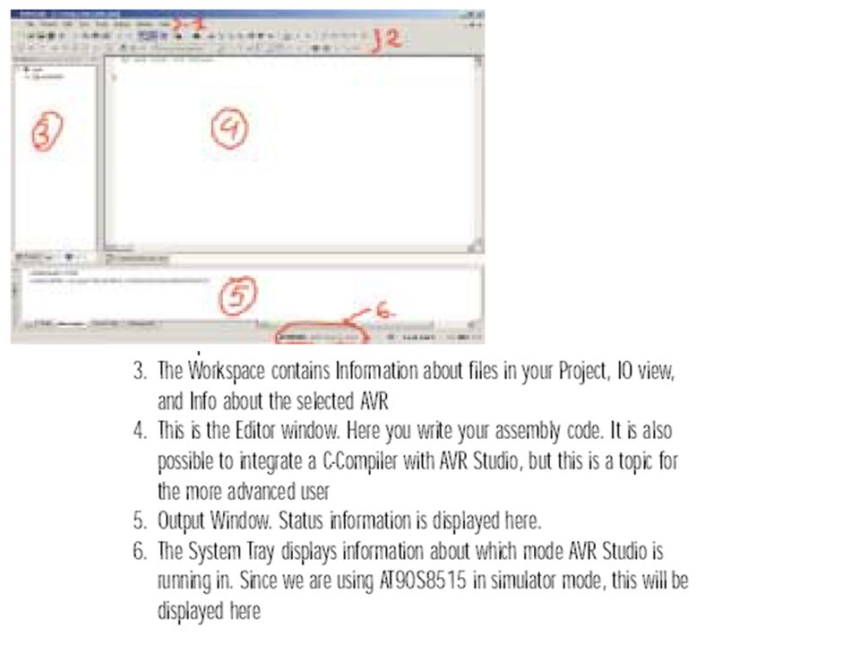
Editor and message windows

4
1)ASSEMBLER DIRECTIVES Change or adjust the way the assembler works with the code
ASSEMBLER DIRECTIVES Change or adjust the way the assembler works with the code")
5
Assembler directives can be divided into the following groups DEFINE SEGMENTS.cseg.dseg.eseg.csegsize.org PROGRAM MEMORY.db.dw.cseg.org EEPROM.db.dw.eseg.org SRAM.byte.dseg.org REGISTER & CONSTANTS.def.equ.set CODING.macro.endmacro.listmac.include ASSEMBLER OUTPUT.device.exit.list.nolist

6
1a) DEFINE SEGMENTS.cseg.dseg.eseg.csegsize.org Word Counter for programs, Byte Counter for SRAM and EEPROM, The values of the Location Counters are defined by.org ; Start program segment
 DEFINE SEGMENTS.cseg.dseg.eseg.csegsize.org Word Counter for programs, Byte Counter for SRAM and EEPROM, The values of the Location Counters are defined by.org ; Start program segment")
7
1b) PROGRAM MEMORY.db.dw.cseg.org 1c) EEPROM.db.dw.eseg.org Define (initialize) values using.DB and.DW
 PROGRAM MEMORY.db.dw.cseg.org 1c) EEPROM.db.dw.eseg.org Define (initialize) values using.DB and.DW")
8
1d) SRAM.byte.dseg.org Define code name for SRAM locations using.BYTE
 SRAM.byte.dseg.org Define code name for SRAM locations using.BYTE")
9
1e) REGISTER & CONSTANTS.def.equ.set Rename Registers Name constants Rename constants (can be used many times with different value)
 REGISTER & CONSTANTS.def.equ.set Rename Registers Name constants Rename constants (can be used many times with different value)")
10
1f) CODING.macro.endmacro.listmac.include Arguments 0 and 1 are r2 and r1 respectively.def pseudo instruction (assembler directive) for sreg in INCLUDE file
 CODING.macro.endmacro.listmac.include Arguments 0 and 1 are r2 and r1 respectively.def pseudo instruction (assembler directive) for sreg in INCLUDE file")
11
1g) ASSEMBLER OUTPUT.device.exit.list.nolist
 ASSEMBLER OUTPUT.device.exit.list.nolist")
12
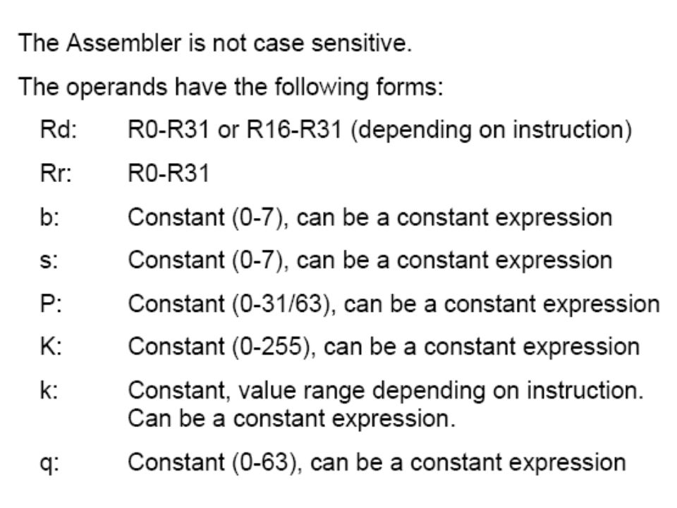
2) EXPRESSIONS Operands Functions Operators 2.1) Operands
 EXPRESSIONS Operands Functions Operators 2.1) Operands")
13
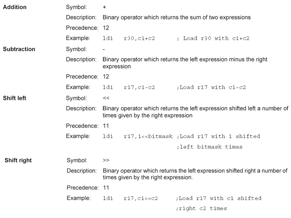
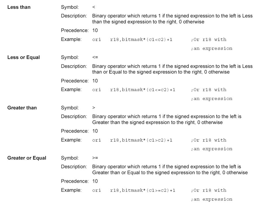
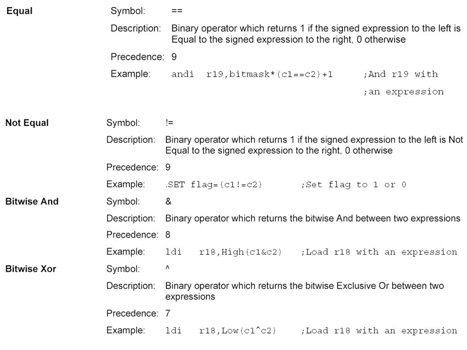
2.2) Functions 2.3) Operators
 Functions 2.3) Operators")
14
Unary operators Binary operators

19
3) AVR STUDIO 4
 AVR STUDIO 4")
29
4.3) Description of the views The following views are available: Output tabs Build window – Message window – Find in files function – Breakpoints Workspace tabs Project view I/O view Register – Processor core register – Stack – I/O register Info view Interrupt vector – AVR package – I/O register Watch view Memory view SRAM – Flash Memory – Register – I/O register – EEPROM Register window Dissasembler window T
 Description of the views The following views are available: Output tabs Build window – Message window – Find in files function – Breakpoints Workspace tabs Project view I/O view Register – Processor core register – Stack – I/O register Info view Interrupt vector – AVR package – I/O register Watch view Memory view SRAM – Flash Memory – Register – I/O register – EEPROM Register window Dissasembler window T")
30
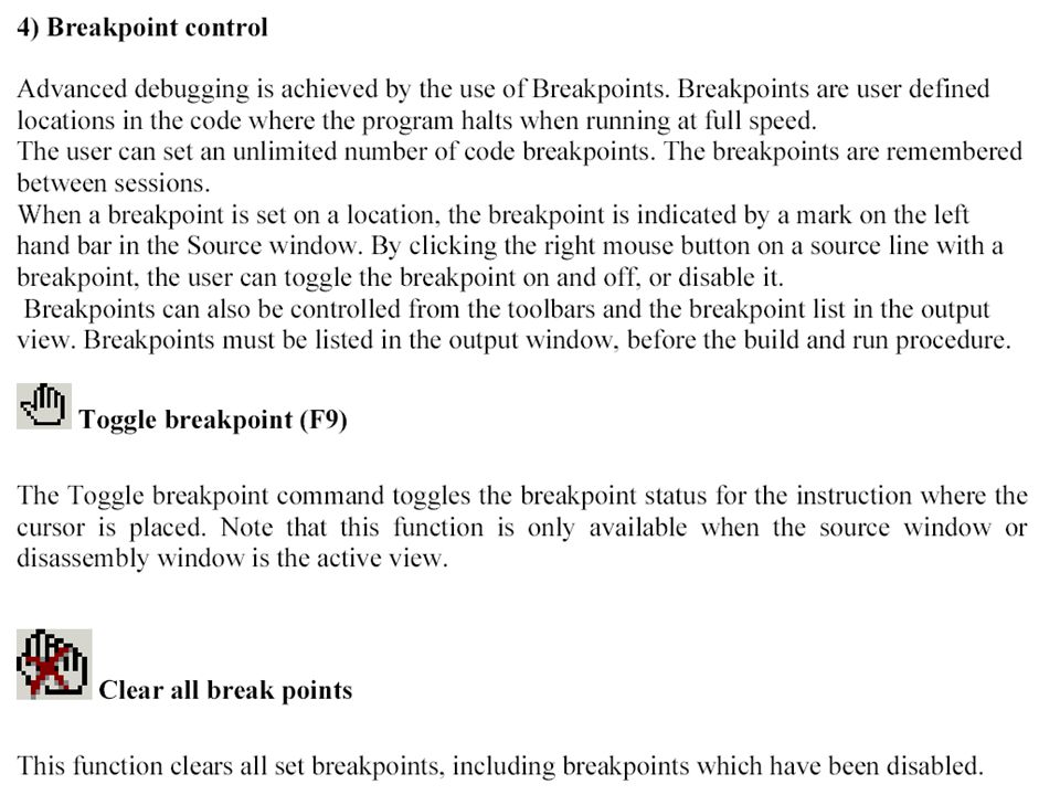
4.3.1) Output tabs Build window – Message window – Find in files function – Breakpoints The Build view. Output from the compiler / assembler is routed to this window. The result of the compilation / assembly can be read here. When compiling or building projects output messages and warnings are printed in this view. Double click on an error or you to the source code location. The key F4 can also be used, and will go to the next error. Breakpoints. Lists all active breakpoints in all modules. Breakpoints can be enabled, disabled and removed in the view. More details in section 4 of the debugging document.

31
4.3.2) Workspace tabs Project view I/O view Register – Processor core register – Stack – I/O register Info view Interrupt vector – AVR package – I/O register 4.3.2.1) Project view
 Workspace tabs Project view I/O view Register – Processor core register – Stack – I/O register Info view Interrupt vector – AVR package – I/O register ) Project view")
32
4.3.2.2) I/O View Register – Processor core register – Stack – I/O register
 I/O View Register – Processor core register – Stack – I/O register")
33
The view has 4 fields of information for the I/O registers, name, value, bits and address.

34
4.3.2.3) Info view Interrupt vector – AVR package – I/O register This view is static and show all interrupts, pin configuration and available IO adresses for the selected device.
 Info view Interrupt vector – AVR package – I/O register This view is static and show all interrupts, pin configuration and available IO adresses for the selected device.")
35
4.3.3) Watch view With the watch window you can view and edit all defined symbols when debugging. Edit Double click on an empty line to type a variable name. Quick watch Highlight the variable you want to watch in the editor and select quickwatch. You can look at the variable and its contents and alternatively add it to the watch view.

36
4.3.4) Memory View Editing Change the value by clicking on the location and type a new value. This can also be done with the ASCII values in the right border (if shown).
..")
37
4.3.5) Register window
 Register window")
38
4.3.6) The Disassembler window The disassembler window shows your program code disassembled. Program execution and AVR instructions can be followed in this view. +000000B9: 2700 CLR R16 Exclusive OR +000000BA: BF05 OUT 0x35,R16 Out to I/O location +000000BB: E800 LDI R16,0x80 Load immediate +000000BC: BF04 OUT 0x34,R16 Out to I/O location

39
4.4) ΑΝΑΠΤΥΞΗ ΚΩΔΙΚΑ AVR Assembler To get started is simple, when AVR Studio loads, select the AVR Assembler from the project dialog box, select a project name directory where the project shall reside, and click finish. A project file is created, an *.asm file is available in the editor window and you are set for writing your first instructions. Check out the online AVR assembler has it's own book where all instructions and directives are explained. In addition, there is context sensitive help in the editor window, just write an instruction, place the cursor on top of the instruction and press F1, and you will get help on the syntax on the selected instruction.

40
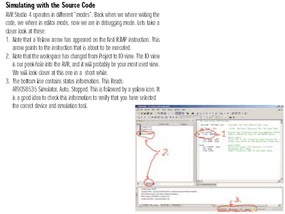
4.5 Simulator The simulator supports all existing new AVR devices, look at the tools and device support for an overview. It simulates not only the CPU, but nearly all the on-chip I/O modules and memory, as well as the I/O ports. Special care has been taken to ensure proper simulation of the device, and there are only small differences between simulated and actual behaviour. The simulator does not connect to outside hardware and has to be stimulated from pre-calculated stimuli files. But as the device is simulated entirely inside the PC memory, the user has extended visibility of all the on-chip functions.

41
If you develop for a specific device in mind you should include the *.def.inc file for the part. Each part has it's own *.inc file that defines all internal registers, bits and a lot of other stuff that makes it simpler for you to write code for the part. In addition the *.inc file sets the device directive for the assembler, letting the assembler know which part you are developing for. The part files are found in the \ProgramFiles\Atmel\AVRTools\AVRAssembler\ΐppnotes folder on your computer. A include file for ATmega8 will typically be named "m8def.inc". You do not have to give a path with the *.inc file as long as it is found in the default directory. Press F7 in order to compile. The result of the compilation will show in the previously described Build view in the output window frame.

43
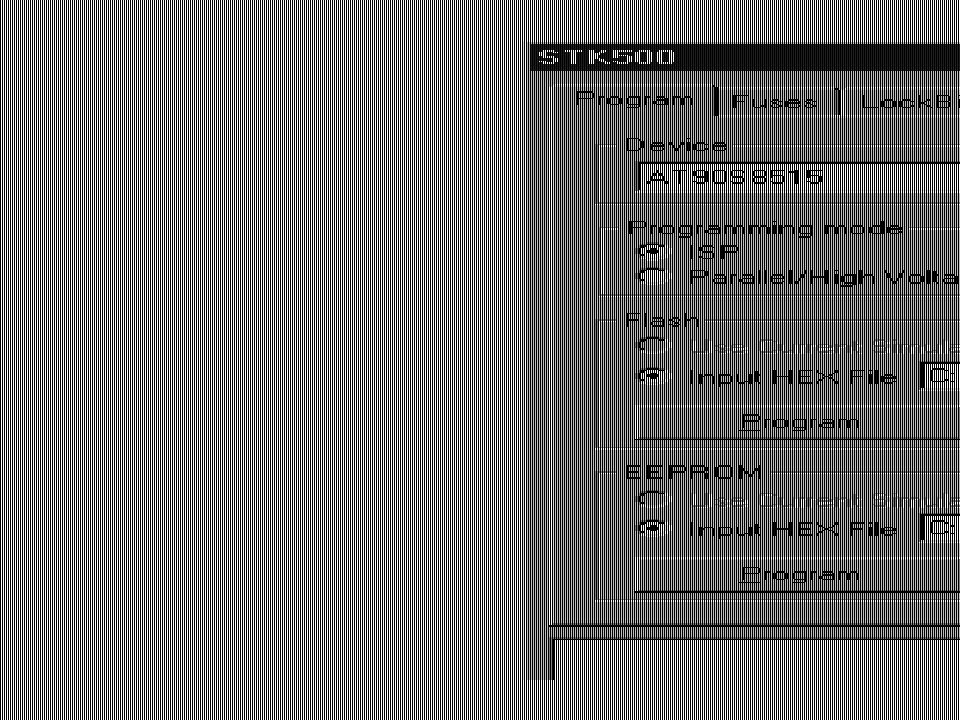
4. 6) Programming the Target AVR Device STK500 is controlled from AVR Studio, version 3.2 and higher. To program a hex file into the target AVR device, select "STK500" from the "tools“ menu in AVR Studio. Select the AVR target device from the pull-down menu on the “Program” tab and locate the intel-hex file to download. Press the "erase" button, followed by the "program" button. The Status LED will now turn yellow while the part is programmed, and when programming succeeds the LED will turn green. If programming fails, the LED will turn red after programming, see the "Trouble-shooting guide" (Help in STK500 user's guide).
 Programming the Target AVR Device STK500 is controlled from AVR Studio, version 3.2 and higher. To program a hex file into the target AVR device, select STK500 from the tools menu in AVR Studio. Select the AVR target device from the pull-down menu on the Program tab and locate the intel-hex file to download. Press the erase button, followed by the program button. The Status LED will now turn yellow while the part is programmed, and when programming succeeds the LED will turn green. If programming fails, the LED will turn red after programming, see the Trouble-shooting guide (Help in STK500 user s guide)..")
48
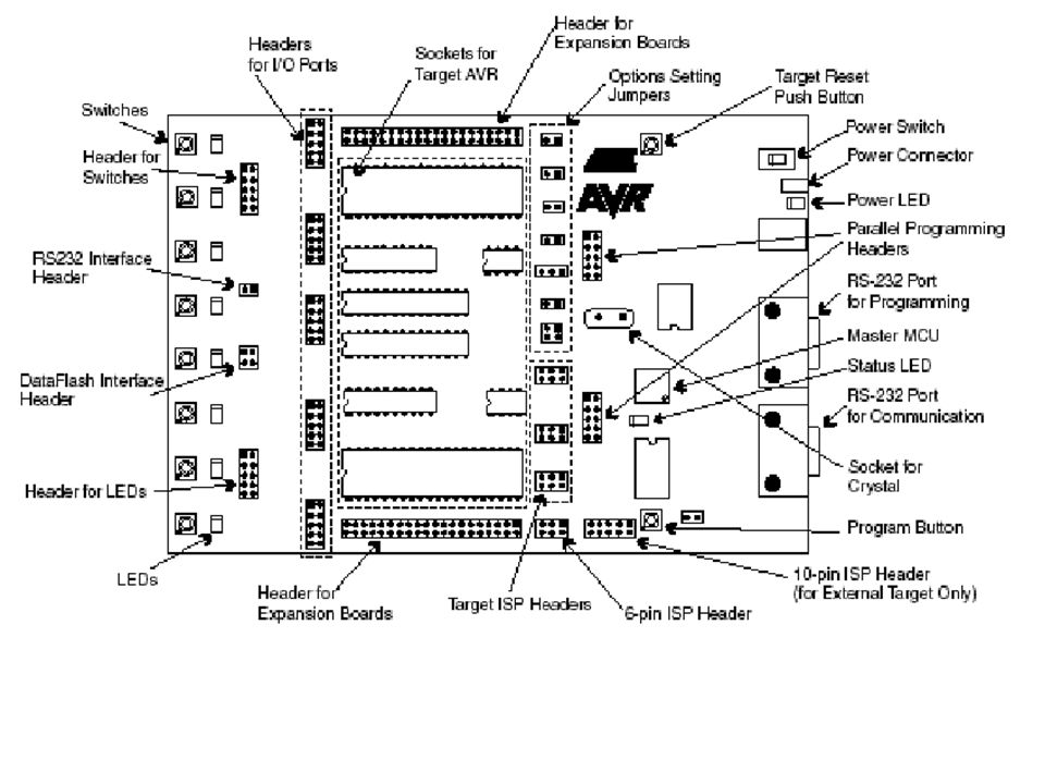
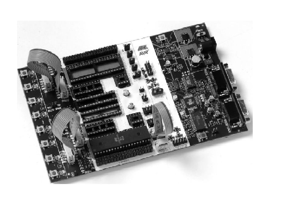
1) 8 διακόπτες 2) 8 LED 3) Δύο σειρές από ακροδέκτες (headers). 4) Μία περιοχή με υποδοχές διαφόρων τύπων AVR (target sockets) και τις υποδοχές για εξωτερικές συνδέσεις των ακροδεκτών των AVR. Κάθε φορά τοποθετείται ένας μόνο AVR. 5) Μία περιοχή με διακλαδωτήρες (jumpers) και μία ενδεικτική λυχνία τροφοδοσίας των υποδοχών.
 Μία περιοχή με υποδοχές διαφόρων τύπων AVR (target sockets) και τις υποδοχές για εξωτερικές συνδέσεις των ακροδεκτών των AVR. Κάθε φορά τοποθετείται ένας μόνο AVR. 5) Μία περιοχή με διακλαδωτήρες (jumpers) και μία ενδεικτική λυχνία τροφοδοσίας των υποδοχών..")
49
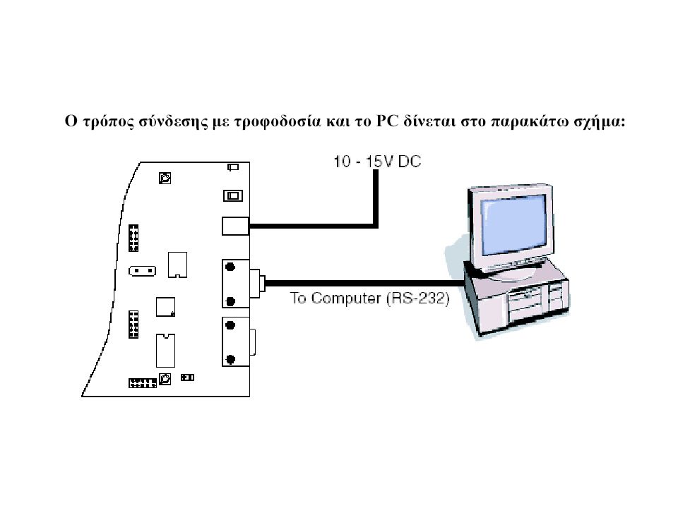
6) Μία σειρά από ακροδέκτες (headers) και υποδοχή για κρύσταλλο. 7) Το τμήμα προγραμματισμού των μνημών των AVR, τους διακόπτες reset και προγραμματισμού και την ενδεικτική λυχνία κατάστασης προγραμματισμού. Υπάρχουν επίσης ένας άλλος AVR ο 8535 (Master AVR) και το κύκλωμα για τις τάσεις RS232, το ΜΑΧ202. 8) Τον διακόπτη τροφοδοσίας, την λυχνία τροφοδοσίας και τις υποδοχές τροφοδοσίας και RS232C (για PC και επιπρόσθετη για άλλη χρήση).
 Το τμήμα προγραμματισμού των μνημών των AVR, τους διακόπτες reset και προγραμματισμού και την ενδεικτική λυχνία κατάστασης προγραμματισμού. Υπάρχουν επίσης ένας άλλος AVR ο 8535 (Master AVR) και το κύκλωμα για τις τάσεις RS232, το ΜΑΧ202. 8) Τον διακόπτη τροφοδοσίας, την λυχνία τροφοδοσίας και τις υποδοχές τροφοδοσίας και RS232C (για PC και επιπρόσθετη για άλλη χρήση)..")
50
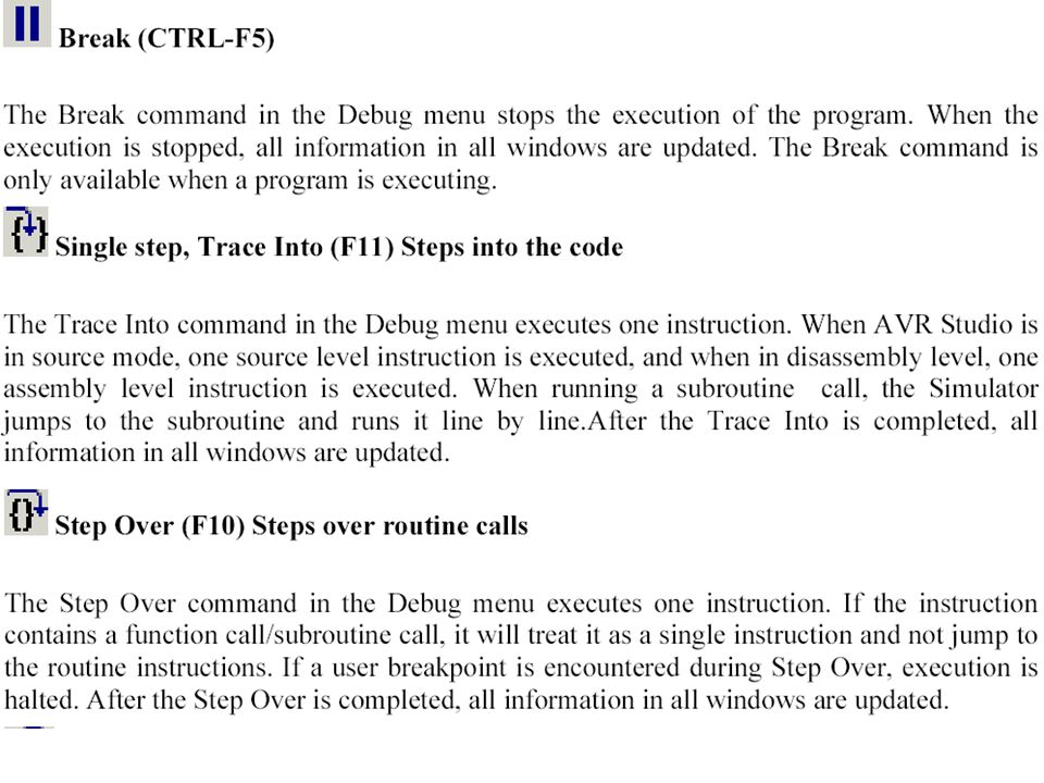
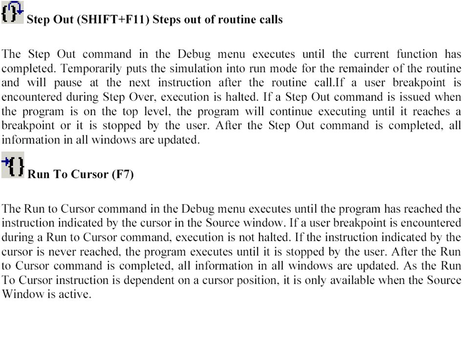
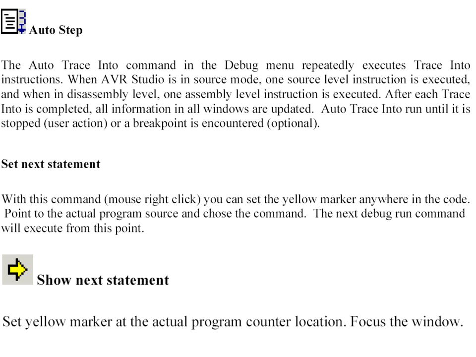
5) Debugging facilities
 Debugging facilities")
57
ΓΕΝΙΚΑ ΣΧΟΛΙΑ ΣΤΗΝ ΑΝΑΠΤΥΞΗ ΚΩΔΙΚΑ ΚΑΙ ΣΤΗΝ ΧΗΣΗ ΤΟΥ AVR STUDIO Σχόλια σε ομάδες εντολών για την περιγραφή της διαδικασίας που υλοποιείται. Συμβατότητα του επιλεχθέντος μοντέλου AVR, με τις επιλογές σε εντολές, τρόπους προσπέλασης, κλπ. Χρήση των συμβατών I/O ports με το συγκεκριμένο μοντέλο AVR. Χρησιμοποιείστε θέσεις υπάρχουσας (εγκατεστημένης για το συγκεκριμένο μοντέλο AVR) SRAM. Μην ξεχνάτε την ψευδοεντολή.include “8515def.inc”. Μη ξεχνάτε τις αρχικές συνθήκες (ιδιαίτερα στο περιβάλλον του simulator) για τους καταχωρητές R0- R31 και SP, καθώς και την εισαγωγή της εντολής sei. Input από PINx και όχι από PORTx. Τερματισμός προγράμματος σας, π.χ. Loop: rjmp loop. Οταν χρησιμοποιείτε τη στοίβα, θα πρέπει να δίνετε αρχικές συνθήκες στον SP. Συνήθως η αρχή της στοίβας ορίζεται στην ramend (γνωστή από την include).
 SRAM. Μην ξεχνάτε την ψευδοεντολή.include 8515def.inc . Μη ξεχνάτε τις αρχικές συνθήκες (ιδιαίτερα στο περιβάλλον του simulator) για τους καταχωρητές R0- R31 και SP, καθώς και την εισαγωγή της εντολής sei. Input από PINx και όχι από PORTx. Τερματισμός προγράμματος σας, π.χ. Loop: rjmp loop. Οταν χρησιμοποιείτε τη στοίβα, θα πρέπει να δίνετε αρχικές συνθήκες στον SP. Συνήθως η αρχή της στοίβας ορίζεται στην ramend (γνωστή από την include)..")
58
Προσοχή στη χρήση αρνητικής λογικής για τον καθορισμό δυαδικών μεταβλητών. Προσοχή στη χρήση των ψευδοεντολών για την ονομασία καταχωρητών. Ξεκινήστε με Open Project, για τον καθορισμό περιβάλλοντος και επεξεργαστή. Αποθηκεύστε τα αρχεία σας στο συγκεκριμένο χώρο users. Αρχεία από την Flash δεν διαβάζονται. Κατά τον προγραμματισμό του 8515, προσοχή στην χρήση του επιθυμητού αρχείου (αυτού που πρόκειται να εκτελέσετε) με το κατάλληλο pathname. Οι κάρτες STK500 διαθέτουν διαφορετικό επεξεργαστή. Ελέγξτε του τύπο του, για να τον χρησιμοποιήσετε στην εντολή include και στο παράθυρο προγραμματισμού της STK500. Μετά από κάθε αλλαγή στον κώδικα, εκτελέστε Build and run και στην συνέχεια προγραμματίστε την κάρτα STK500. Στο στάδιο της αποσφαλμάτωσης, βρόχοι καθυστέρησης καλύτερα να ορίζονται σαν σχόλια (comment out). Προσεκτική επιλογή των Breakpoints.
 με το κατάλληλο pathname. Οι κάρτες STK500 διαθέτουν διαφορετικό επεξεργαστή. Ελέγξτε του τύπο του, για να τον χρησιμοποιήσετε στην εντολή include και στο παράθυρο προγραμματισμού της STK500. Μετά από κάθε αλλαγή στον κώδικα, εκτελέστε Build and run και στην συνέχεια προγραμματίστε την κάρτα STK500. Στο στάδιο της αποσφαλμάτωσης, βρόχοι καθυστέρησης καλύτερα να ορίζονται σαν σχόλια (comment out). Προσεκτική επιλογή των Breakpoints..")
59
Προσεκτική παρακολούθηση των I/O window και Memory windows. Η χρήση του watch view είναι χρήσιμη για την παρακολούθηση των τιμών των μεταβλητών που ορίζονται με κωδικό όνομα. Οταν το πρόγραμμα εκτελείται στον target AVR στην STK500, για να βεβαιωθείτε οτι το πρόγραμμα σας διέρχεται από συγκεκριμένη περιοχή χρησιμοποιείτε κατάλληλες ενδείξεις στα LEDs και προσωρινές στάσεις στην εκτέλεση του προγράμματος με αέναο βρόχο ή με πίεση κατάλληλου πλήκτρου. Η ορθή λειτουργία του προγράμματος στο περιβάλλον του simulator, δεν σας εξασφαλίζει και ορθή λειτουργία στην κάρτα STK500. Ιδιαίτερη προσοχή στη χρήση διακοπτών και LEDs (αρνητική λογική).
..")
60
Debug toolbar

61
Views toolbar

Παρόμοιες παρουσιάσεις


 polynomial (X, X). polynomial (Term, X) :- number (Term).>")


 Τεχνολογία ΛογισμικούSlide 39 with Pump, Temperature_dial, Sensor, Globals, Alarm; use Globals ; procedure.>")


